10
21
22
21
22
21
22
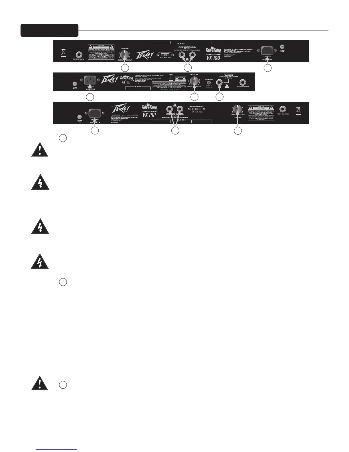
AC POWER INLET:
This is the receptacle for an IEC line cord, which provides AC power to the unit. Connect the line cord to
this connector to provide power to the unit. Damage to the equipment may result if improper line volt-
age is used. (See line voltage marking on unit).
Never break off the ground pin on any equipment. It is provided for your safety. If the outlet used
does not have a ground pin, a suitable grounding adapter should be used and the third wire should be
grounded properly. To prevent the risk of shock or re hazard, always make sure that the amplier and
all associated equipment is properly grounded.
NOTE: FOR UK ONLY
As the colors of the wires in the mains lead of this apparatus may not correspond with the colored mark-
ings identifying the terminals in your plug, proceed as follows: (1) The wire which is colored green and
yellow must be connected to the terminal which is marked by the letter E, or by the earth symbol, or
colored green or green and yellow. (2) The wire which is colored blue must be connected to the terminal
which is marked with the letter N, or the color black. (3) The wire which is colored brown must be con-
nected to the terminal which is marked with the letter L, or the color red.
To avoid the risk of electrical shock, do not place ngers or any other objects into empty tube sockets
while power is being supplied to unit.
TEXTURE
This a new patent pending feature available only from Peavey, used to ne-tune the power sensitivity,
response, and “break-up” of the power amp section of your Valve King™ amplier. Normal, full-power,
Class A/B operation results when the TEXTURE (#21) control is set at its full clockwise (wide open) posi-
tion and should be used as a starting point when setting this control. As the TEXTURE (#21) control is
rotated counter-clockwise, the effect of one half of the 6L6GC power tubes is progressively subtracted
from the circuit, while the gain of the driver tube is slowly increased. The driver's low-frequency
response is also altered, along with the gain, resulting in more even-ordered harmonic distortion from
your power amp, even at lower-than-stage-volume settings. Finally, with the TEXTURE (#21) knob in
the full counter-clockwise position, the result is a real single-ended power amp section that operates
and responds exactly like a true Class A power amp, driven by a real single-ended high-gain tube stage.
This setting still allows the unused power tube(s) to draw idle current, thus retaining the efciency of
the standard Class A/B topology. In this mode, power output is also reduced by as much as 60% versus
maximum rated power.
EXTERNAL SPEAKER JACK
Provided for connection of external speaker cabinet(s). Minimum external speaker impedance is
16 Ω on the Valve King™112. This disconnects the internal speaker in the Valve King™ 112.
Load Impedance is selectable via the IMPEDANCE SELECTOR (25) on the Valve King™ 212 and
Valve King™ 100
Rear Panel
20
21
22
20
20
20

 Loading...