13 of 58
ISSUED: 10-30-09 SHEET #: 095-9297-7 07-11-11
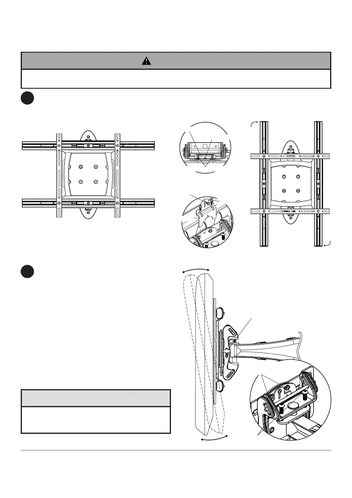
FOR PORTRAIT OR LANDSCAPE DISPLAY ORIENTATION: Remove two M5 x 12mm screws, one M5 x 6mm
screw and rotation block from top of tilt head as shown in top view and rear view. Gently grasp sides of display and
rotate display into portrait or landscape position as shown in fi gure 5.1 and reinstall rotation block with two
M5 x 12mm screws and one M5 x 6mm screw. NOTE: M5 x 6mm screw required in landscape orientation only.
Tilt Adjustment: Adjust tension knob on side of
mount to desired tension to enable tilt adjustment and
balance your display size and weight. Push or pull
from top or bottom of display to adjust tilt as shown.
The tilt can be adjusted to a maximum of 10° forward
or 5° backward. Retighten tension knob. NOTE: For
larger displays, tension screw on opposite side of
mount may need to be tightened using 5/32" allen
wrench (M).
Roll Adjustment: Rotate display 5° clockwise or
counter-clockwise, level display then tighten
M5 x 10mm screws using 5mm allen wrench (I) as
shown in detail 1.
Vertical Height Adjustment: Tighten or loosen two
M8 x 40mm screws an equal number of turns to
achieve ± 1" of vertical height adjustment as shown in
detail 1.
Adjustment of Flat Panel Display
5
6
TENSION KNOB
DETAIL 1
REAR VIEW
TOP VIEW
fi g. 5.1
M5 X 10MM
SCREWS
M8 X 40MM
SCREWS
• Do not tighten screws with excessive force.
• Be careful not to pinch fi ngers when opening and
closing mount from the wall.
CAUTION
• M10 x 15mm screws (E) must be securly tightened before changing orientation of wall arm (A). Failure to lock
adapter bracket can cause display to come off of mount.
WARNING
ROTATION BLOCK
ROTATION BLOCK
M5 X 12MM SCREWS
M5 X 6MM SCREWS
M5 X 12MM
SCREWS
M5 X 6MM
SCREWS