c. The required flow is calculated based on the design
temperature difference from the return to the supply
of the boiler. For a PFC-460 boiler with a design
temperature difference of 20°F, the calculation is as
follows:
Output 438,000
Required Flow =
________
=
_________
= 43.8 GPM
Δ
T x 500 20 x 500
d. The boiler pressure drop for various flow rates can
be determined using Figure 4.3, the P
UREFIRE
®
Boiler Circulator Sizing Graph.
e. Table 4.4 provides the flow rate and pressure drop
information that corresponds to various system
temperature rise values (ΔT). The pressure drop
shown is for the boiler only. If there is significant
pressure drop in the system, this should be
included when specifying circulators.
f. Table 4.5 provides a list of recommended
circulators for boilers on a secondary loop of a
primary/secondary system which uses water as a
heating medium.
g. Special consideration must be given if a glycol
based anti-freeze solution is used as a heating
medium. Propylene glycol has a higher viscosity
than water, therefore the system pressure drop will
be higher.
18 18
WATER PIPING AND CONTROLS
PUREFIRE
®
Model
Boiler Input
Btu/hr (kW)
Gross Output
Btu/hr (kW)
PFC-460 460,000 (134.8) 438,000 (128.8)
Table 4.3: Boiler Inputs and Outputs
Figure 4.3: PUREFIRE
®
Circulator Sizing Graph (General Pump – Primary/Secondary)
Pressure Drop (Ft. of Water)
PFC-460 Pressure Drop vs. Flow
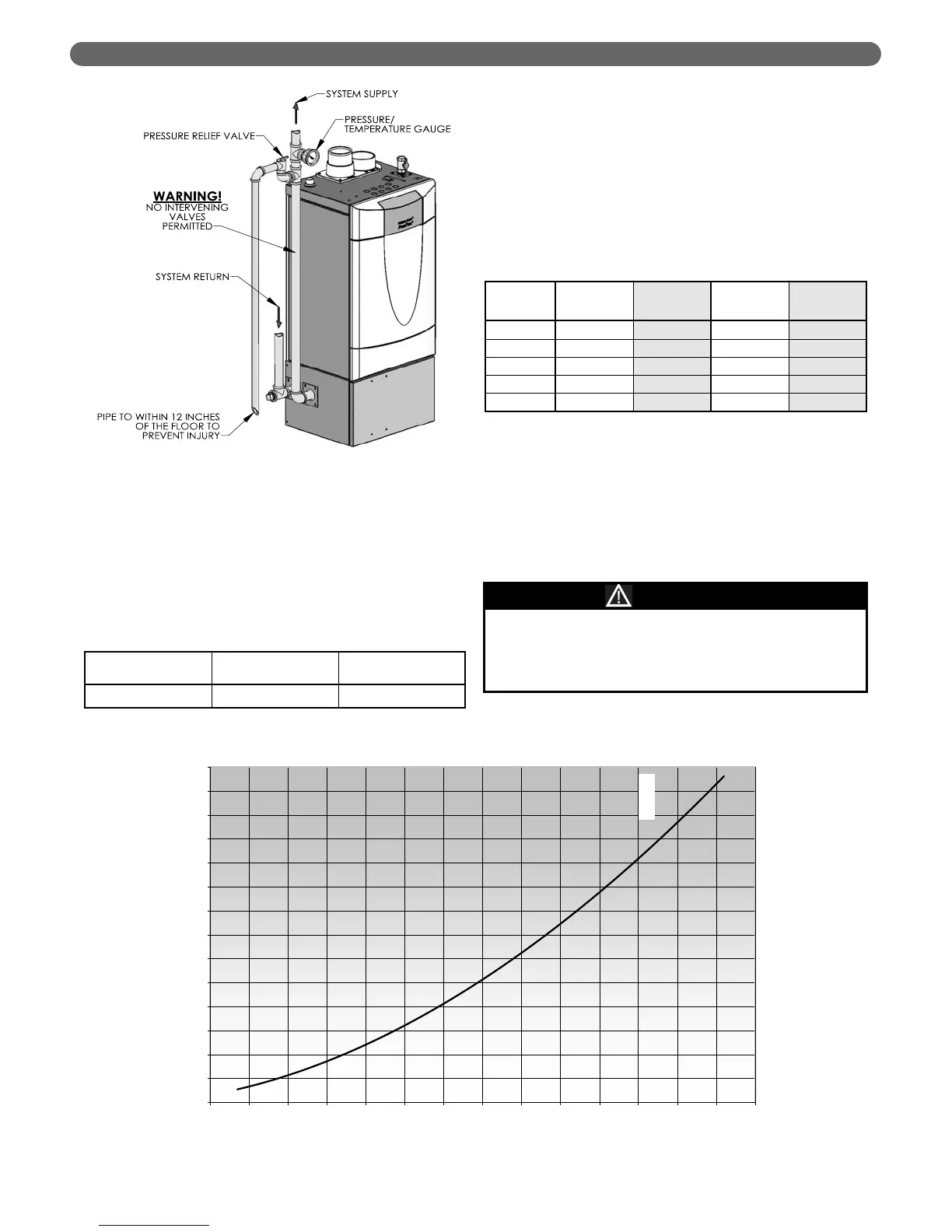
Figure 4.2: Relief Valve Installation – PFC-460
Table 4.4: Flow Rate vs. Pressure Drop for Various
Boiler Temperature Rise Values
ΔT
(°F)
GPM FT LPM m
40 21.9 6.71 82.9 2.05
35 25.0 8.60 94.6 2.62
30 29.2 11.46 110.5 3.49
25 35.0 16.10 132.5 4.91
20 43.8 24.39 165.8 7.43
The circulator sizing given is for primary/secondary
installations only. The system circulators must be
sized based on the flow and pressure drop
requirements of the system.
NOTICE