35
8. BOILER CONTROL: OPERATION
A. CONTROL OVERVIEW
The PUREFIRE
®
boiler control is one of the primary safety
devices for the boiler. It controls the ignition sequence,
temperature limits, circulators and gas flow to the boiler. It
also provides many unique features.
The control provides 8 central heating modes and 3
domestic hot water modes. To provide maximum
flexibility, several special features are also included.
1. Central Heating (CH) Modes:
The P
UREFIRE
®
boiler control allows the installer to
choose from several different central heating modes.
The following table shows the central heating modes. In
addition, the table shows the display text associated with
each CH mode and a brief description of the operation.
2. Domestic Hot Water (DHW) Modes:
The P
UREFIRE
®
boiler control also allows the installer
to choose from three different DHW modes.
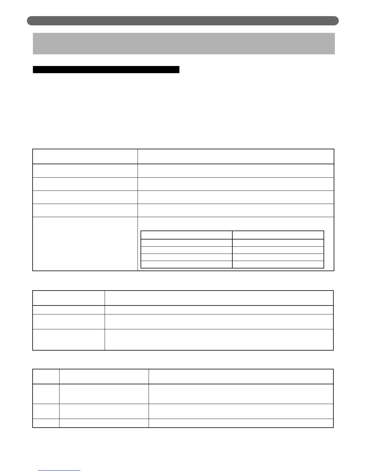
Table 8.1: Central Heating (CH) Modes
Central Heating Mode Description
0 (Indoor Thermostat) Default
Boiler operates when CH TSTAT terminals (#1 & #2) are closed targeting a fixed setpoint
regardless of heating load.
1 (Thermostat and Outdoor Reset)
Boiler operates when CH TSTAT terminals (#1 & #2) are closed targeting a variable setpoint
based on outdoor temperature.
2 (Permanent Demand and Outdoor Reset)
Boiler operates to maintain a variable setpoint based on outdoor temperature. When CH
TSTAT terminals (#1 & #2) are closed, 18°F is subtracted from the calculated setpoint.
3 (Permanent Demand and Setpoint)
Boiler operates to maintain a fixed setpoint. When CH TSTAT terminals (#1 & #2) are
closed, 18°F is subtracted from the setpoint.
4 (Analog 0-10 VDC Input – Setpoint)
Boiler operates on setpoint from an external device (BMS) based on a 0-10 VDC analog signal
to provide setpoint.
Input Signal Target Setpoint
0-1.5 VDC OFF
2 VDC 60°F
6 VDC 123°F
10 VDC 189°F
Table 8.2: Domestic Hot Water (DHW) Modes
Domestic Hot Water Mode Description
0 (No DHW) No DHW tank is used.
1 (DHW Tank with sensor)
The domestic water tank is equipped with a temperature sensor. The PUREFIRE
®
control modulates the boiler
firing rate based on tank temperature
2 (DHW Tank with thermostat)
The domestic water tank is equipped with a thermostat. The PUREFIRE
®
control responds to the demand from
the thermostat and modulates the boiler firing rate targeting the DHW boiler setpoint. If no domestic hot water
tank is connected, this feature will not function.
Table 8.3: Pump Modes
Pump
Mode
Display Text Brief Description
0 DHW or CH & DHW pump
The General pump is always on when the burner is on. The CH pump runs on CH
demand. The DHW pump runs on DHW demand. Either the CH or DHW pump runs;
they never run at the same time
1 General pump with 3-way valve
The General pump is always on when burner is on. A line voltage (120 VAC) 3-way
valve is operated to supply water to the DHW tank.
2 Manifold with pump for DHW This mode is not used for most operations. Consult factory if needed.
BOILER CONTROL: OPERATION