33
ELECTRICAL CONNECTIONS
4. Note that the service switch does not disconnect
power to the convenience outlet.
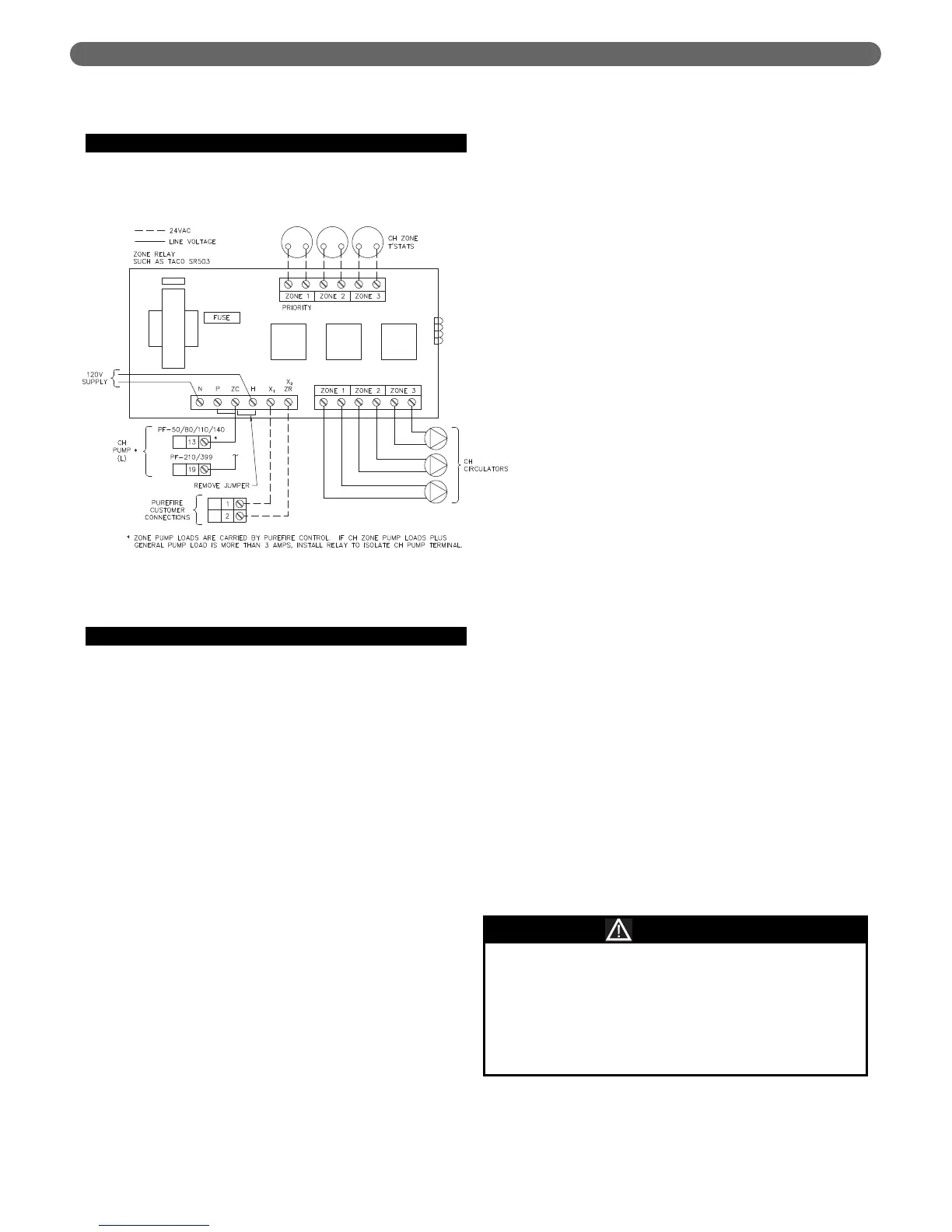
C. ZONE CIRCULATOR WIRING
Wiring for a typical circulator zone relay is shown in
Figure 7.3.
D. INTERNAL WIRING
Figure 7.4 shows the complete boiler wiring schematic for
PFC-460 boilers. The following is a list of internal wiring
components:
1. User Interface: The user interface is attached to the
front of the electrical junction box and is accessible by
removing the tinted lens on the front of the boiler.
This interface allows users and installers to
communicate with the control.
2. Supply/Return Sensors: These component, located on
the left header are a pair thermistors that provide
supply and return water temperature information to
the control. Be sure to use only a P
UREFIRE
®
supply
thermistors for this boiler.
3. Limit Switch: This component is a bi-metal switch that
will prevent the boiler from reaching temperatures
above 203°F (95°C) to prevent damage to the boiler.
Be sure to use only a P
UREFIRE
®
supplied switch
4. Flue Sensor: This thermistor provides flue temperature
information to the control. It is located in the back of
the electrical junction box behind the user interface.
5. Condensate Drain Float Switch: This switch is
mounted in the condensate collector below the heat
exchanger in the rear of the cabinet.
6. Service Switch: The service switch interrupts the
power to the P
UREFIRE
®
boiler to allow service to be
performed.
7. Convenience Outlet: The convenience outlet is
provided for a condensate pump during operation. It
is not switched with the service switch to allow its use
for lighting during maintenance.
8. Flame Sensor: The flame sensor uses the principal of
flame rectification to sense the burner flame. This is
located on the right side of the heat exchanger front
plate. After ignition, the control also senses flame
through the ignition electrode.
9. Gas Valve: The gas valve is connected through a
special cord and connector. The connector is attached
to the valve with a screw.
10. Ignition Electrode: This electrode is located on the left
side of the heat exchanger front plate. A 10,000 volt
charge is initiated by the control to provide a spark for
lighting the burner. After the burner lights, and no
spark is present, the control uses this electrode as a
second source of flame detection.
11. Combustion Air Fan: The combustion air fan has two
connections. There is a 120 volt power connection (3-
wire) and a low voltage control connection (4-wire).
12. Blocked Vent Switch: This switch is used to detect a
blockage in the exhaust vent.
13. P
UREFIRE
®
Link Adapter (Green Plug): The adapter is
used by Factory Engineers to review control settings.
14. Burner Plate Switch: This switch (Part #50045) is
used to detect overheating of the burner plate,
primarily caused by broken insulation on the inside of
the burner plate.
15. Thermal Fuse: This fuse (stock code #54466) is used
to detect overheating at the rear of the heat exchanger
behind the combustion chamber. If this device causes
an open circuit then it requires replacement. Before
replacing the switch, inspect the target wall inside the
combustion chamber at the rear to be sure it is intact.
16. Relay Module: This module, located in the control
cabinet, prevents overcurrent of the main boiler
control by isolating the pump current. This allows a
maximum current of 10 Amps on each circulator (CH,
DHW and GEN) to be connected.
Figure 7.3: Typical Zone Circulator Relay Wiring
IF the fuse blows in the boiler control, a spare fuse
(found in a holder on the control cover) can be used
as a replacement. DIAGNOSE POSSIBLE CAUSES
FOR BLOWN FUSE BEFORE REPLACING. Additional
fuses can be ordered as need from your Peerless
Boiler Distributor (Part #5650). See Figure 10.1 for
location of Boiler Control fuse and spare fuse.
NOTICE