52
calculated based on the Calculated Setpoint
Max offset up. Similarly, if the system target is
above its target a calculated negative offset based
on the Calculated Setpoint Max offset down
is applied. The maximum increased setpoint
temperature is 195°F (91°C).
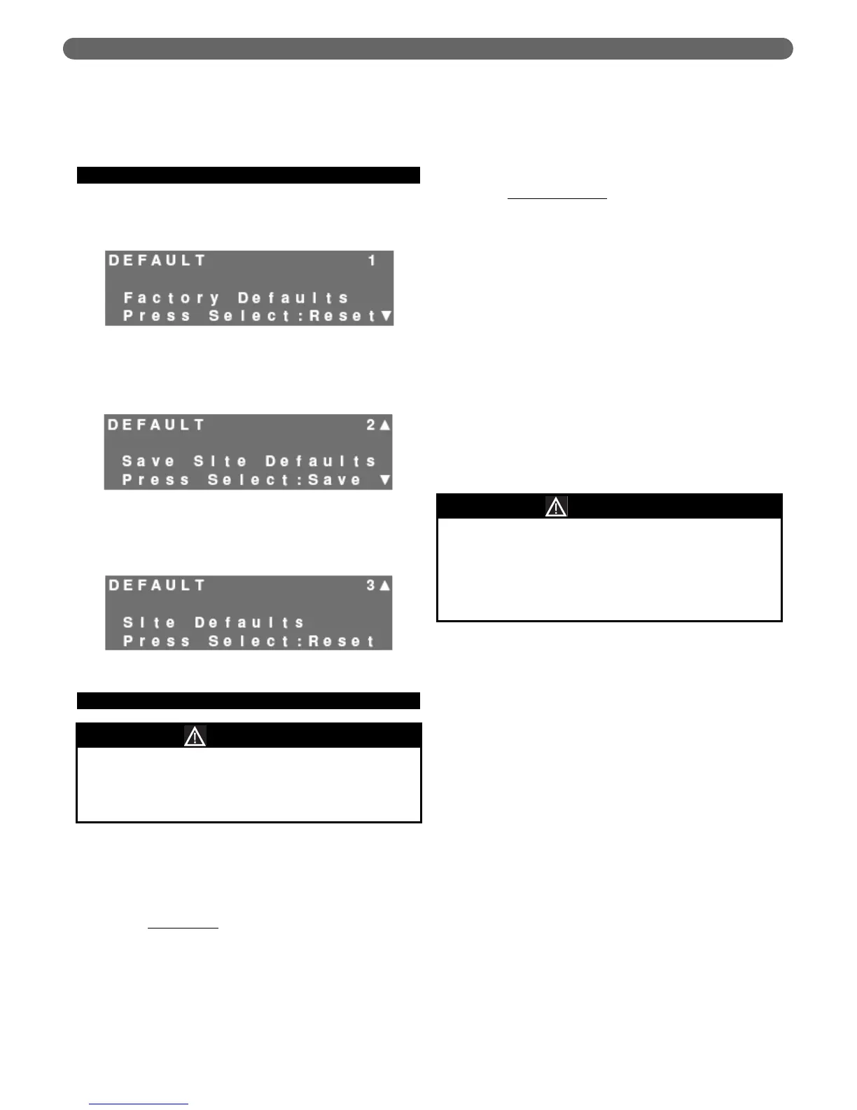
E. DEFAULTS
1. Factory Defaults – Restore: By pressing the
“Select” key while in the “Factory Defaults” screen.
All factory settings will be restored on the control.
2. Site Defaults – Save: To save the current settings as
“Site Defaults,” press the “Select” key while in the
following menu.
3. Site Defaults – Reset: To restore the “Site Defaults,”
press the “Select” key while in the following menu.
F. MULTIPLE BOILERS
1. PUREFIRE
®
boiler controls can operate together to
control up to 16 boilers for one central heat or domestic
hot water demand. Only the addition of a system
sensor (54156) is required to provide this operation.
2. Overview:
a. Master Boiler
: In a multiple boiler system, a boiler
designated as the “Master” boiler controls the
function of the boiler system.
• Attached to a system sensor which monitors
the system water temperature.
• Can also be connected to an outdoor sensor
(54112), included with each boiler, as well as
an optional DHW sensor (54157) or a
standard DHW thermostat.
• Determines which boiler operates first (lead)
and when to bring on additional boilers.
• Determines the setpoint temperature of
individual boilers.
• Shuts down all boilers in the system if the
LWCO contacts are opened.
b. Dependent Boilers
: The “dependent” boilers
operate at the setpoint temperature that the
Master boiler specifies.
• Maintain all of their own safety parameters
such as safety limit, vent temperature limit,
and freeze protection.
• Control their own general circulator that is
energized whenever there is a call for either
Central Heat or Domestic Hot Water.
• Shuts down the individual boiler if the
dependent boiler LWCO contacts are opened.
3. System Piping & Wiring:
a. Multiple boilers with multiple zones with zone valves.
• Figure 8.49 shows a typical system which uses a
CH circulator, a DHW circulator and zone valves
to distribute the heating load to the building.
• A three zone valve control panel (not included)
controls circulation to individual zones.
• A call from any of the heating zones initiates a
contact closure from the zone relay across the
CH thermostat connections (terminals #1 &2)
on the master boiler. This initiates ignition of
the “lead” boiler and its general pump. In
addition, the CH circulator is energized.
• A call for domestic hot water can either be
initiated internally by the control when it sees
a drop in indirect tank temperature or by a
tank thermostat. In either case, the lead boiler
is ignited and its general pump operates. The
DHW circulator is also energized.
b. Multiple boilers with multiple zones with zone
circulators.
• Figure 8.50 shows a typical system which uses
a circulator zone control panel to control the
central heating zones.
• The DHW circulator can be operated by the
priority zone or can be connected directly to
the boiler (as shown). In either case, the
priority zone cannot be used for heating.
• Again, a call for heat from any of the heating
zones causes the master boiler to initiate
operation of the lead boiler and its general
circulator. The CH circulators are controlled by
the zone control relay panel.
Figure 8.46: Restore Factory Defaults Screen
Figure 8.47: Save Site Defaults Screen
Figure 8.48: Restore Site Defaults Screen
Before selecting cascade operation, connect the
System sensor to terminals #7 & #8. Failure to do
this will result in a blinking screen warning as
covered in Section 10.D.
NOTICE
The central heating (CH) circulator and the domestic
hot water (DHW) circulator must be sized in
accordance with good Engineering practices based
on the required flow and pressure drop of the
system. Failure to do so may result in system
performance problems.
NOTICE
BOILER CONTROL: OPERATION