39
C. USER MENU
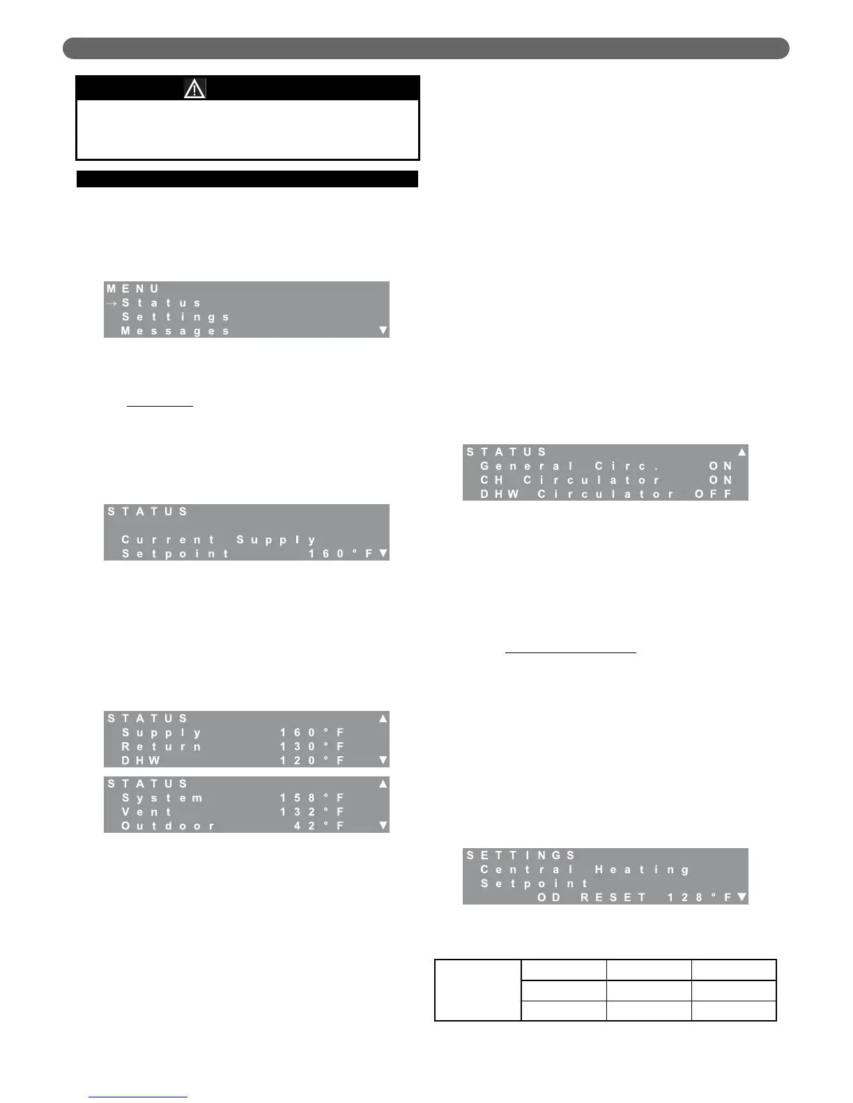
To access the user menu, simply press the “Menu” key on
the LCD display. Use the “▲” and “▼” keys on the
display to move the cursor to the desired selection.
Pressing “Select” will access the submenu for the
selection. The submenus are described in detail below.
1. LCD Status Menu
Status Menu
: The user status menu gives the user or
installer access to basic information about the boiler
system. The first screen shows the Current Supply
Setpoint. If the boiler is in CH Mode 0, 2 or 6, this is
the temperature that the boiler targets. As the boiler
approaches this target, the burners will modulate their
input.
The next screens show temperature values read by the
temperature sensors in the control system. The supply
and return temperatures are measured at the header
on the outlet side of the heat exchanger. There is a
supply and return sensor for each burner. In addition
to the supply and return sensors, there is a header
(system) sensor on the boiler supply (outlet) pipe.
Typical Values for Water Sensors:
(Supply/Return/System/DHW): 70°F (21°C) to 200°F
(93°C).
A value of 14°F (-10°C) indicates an open sensor and
a value of 244°F(118°C) indicates a short for these
sensors.
Typical Values for the Vent Sensor are: 70°F (21°C) to
200°F (93°C).
A value of 50°F (-10°C) indicates an open sensor and
a value of 244°F(118°C) indicates a short. Since
boilers installed in low temperature environments such
as a garage may experience vent temperatures below
50°F, the control works as follows:
a. If the Vent Temperature Sensor reads less than
50°F, the boiler will continue to operate normally,
unless,
b. If the return temperature exceeds 80°F (27°C) or
the supply temperature exceeds 120°F (49°C) the
burners will operate at their minimum modulation
until the call for heat ends or the vent temperature
exceeds 50°F.
The outdoor sensor temperature should correspond to
the current outdoor temperature. If the sensor is
mounted in direct sunlight or near an appliance
exhaust vent, erratic operation can result due to large
changes in the apparent outdoor temperature.
A value of -40°F (-40°C) indicates an open sensor and
a value of 244°F(118°C) indicates a short for this sensor.
The final screen of the status menu provides
information on the status of each of the circulators.
2. LCD Settings Menu
The user settings menu provides access to basic
settings on the P
UREFIRE
®
control. After choosing the
“Settings Menu” the Central Heating Setpoint menu
appears. To access the other menus, press the “
M”
key. Some of the menus shown below will not appear
depending on the CH or DHW mode chosen.
a. Central Heating Setpoint
: Depending on the CH
Mode chosen (in the Installer Menu), the user may
be able to adjust the boiler water temperature that
is targeted by the control on a central heat
demand. If the CH Mode is 1 or 2 (Outdoor
Reset), this screen will show “OD RESET” along
with the target temperature calculated by the
control algorithm. The user is not allowed to
override the calculated temperature. If CH Mode 0
or 6 is chosen, the target temperature can be
changed by pressing the “Select” key and using the
“L” and “
M” keys to increase or decrease the
value. The following shows the range and default
values for the Central Heating Setpoint.
Figure 8.2: User Menu
Figure 8.3: Status – Supply Setpoint
Figure 8.4: Status – Temperature
Figure 8.5: Status – Circulators
Figure 8.6: Settings – CH Setpoint
Subsections C-E of this supplement are to be used in
lieu of subsections C-I in the PF8248 I,O,&M
instructions.
NOTICE
Table 8.6: CH Setpoint Range & Defaults
Central
Heating
Setpoint
Minimum Maximum Default
50°F 195°F 160°F
10°C 91°C 71°C
BOILER CONTROL: OPERATION