19
11. Indirect Water Heater: An indirect water heater should
be piped to a dedicated zone. The P
UREFIRE
®
boiler
provides electrical terminals for connecting a domestic
hot water (DHW) circulator. Examples of piping for
the indirect water heater are shown under subsection
“D”, System Piping of this section.
D. SYSTEM PIPING
1. Figure 4.4 shows a single boiler with multiple heating
zones. In this case, the DHW zone is piped in parallel
to the heating zones on the primary loop.
2. For a single boiler with one heating zone and one
DHW zone which utilizes an indirect water heater like
the Peerless
®
Partner
®
, pipe the boiler as shown in
Figure 4.5. In systems like this, the DHW circulator
must be sized to provide the minimum flow rate
through the boiler.
3. In Figure 4.6 an additional boiler is added and more
heating zones are shown. Notice that the two boilers
are piped in parallel on the secondary loop. This
maximizes the efficiency of the boilers since the lowest
temperature system water is returning to both boilers.
4. Figure 4.7 shows a multiple boiler system with several
different types of heat distribution units. This system
illustrates how different temperature zones can be
supplied from the same source by blending supply
and return water to the zone.
5. In Figure 4.8 zone valves are used instead of zone
circulators. Notice that the system is piped using
reverse return piping to help balance the flow through
the zones. If the zone lengths vary balancing valves
are required on each loop.
E. FREEZE PROTECTION
1. Glycol for hydronic applications is specially formulated
for heating systems. It includes inhibitors which prevent
the glycol from attacking metallic system components.
Make sure that the system fluid is checked for correct
glycol concentration and inhibitor level.
2. Use only inhibited polypropylene glycol solutions of
up to 50% by volume. Ethylene glycol is toxic and
can chemically attack gaskets and seals used in
hydronic system.
3. The anti-freeze solution should be tested at least once
per year and as recommended by the manufacturer of
the product.
4. Anti-freeze solutions expand more than water. For
example, a 50% by volume solution expands 4.8%
with a 148°F temperature rise while water expands
about 3% for the same temperature increase.
Allowance for this expansion must be considered in
sizing expansion tanks and related components.
5. The flow rate in systems utilizing glycol solutions
should be higher than in a water system to
compensate for decreased heating capacity of the fluid.
6. Due to increased flow rate and fluid viscosity, the
circulator head requirement will increase. Contact the
pump manufacturer to correctly size the circulator for
a particular application based on the glycol
concentration and heating requirements.
7. A strainer, sediment trap, or some other means for
cleaning the piping system must be provided. It
should be located in the return line upstream of the
boiler and must be cleaned frequently during the
initial operation of the system. Glycol is likely to
remove mill scale from new pipe in new installations.
8. Glycol solution is expensive and leaks should be
avoided. Weld or solder joints should be used where
possible and threaded joints should be avoided.
Make-up water should not be added to the system
automatically when glycol solution is used. Adding
make-up water will dilute the system and reduce the
ability of the solution to protect from freezing.
9. Check local regulations to see if systems containing
glycol solutions must include a back-flow preventer or
require that the glycol system be isolated from the
water supply.
10. Do not use galvanized pipe in glycol systems.
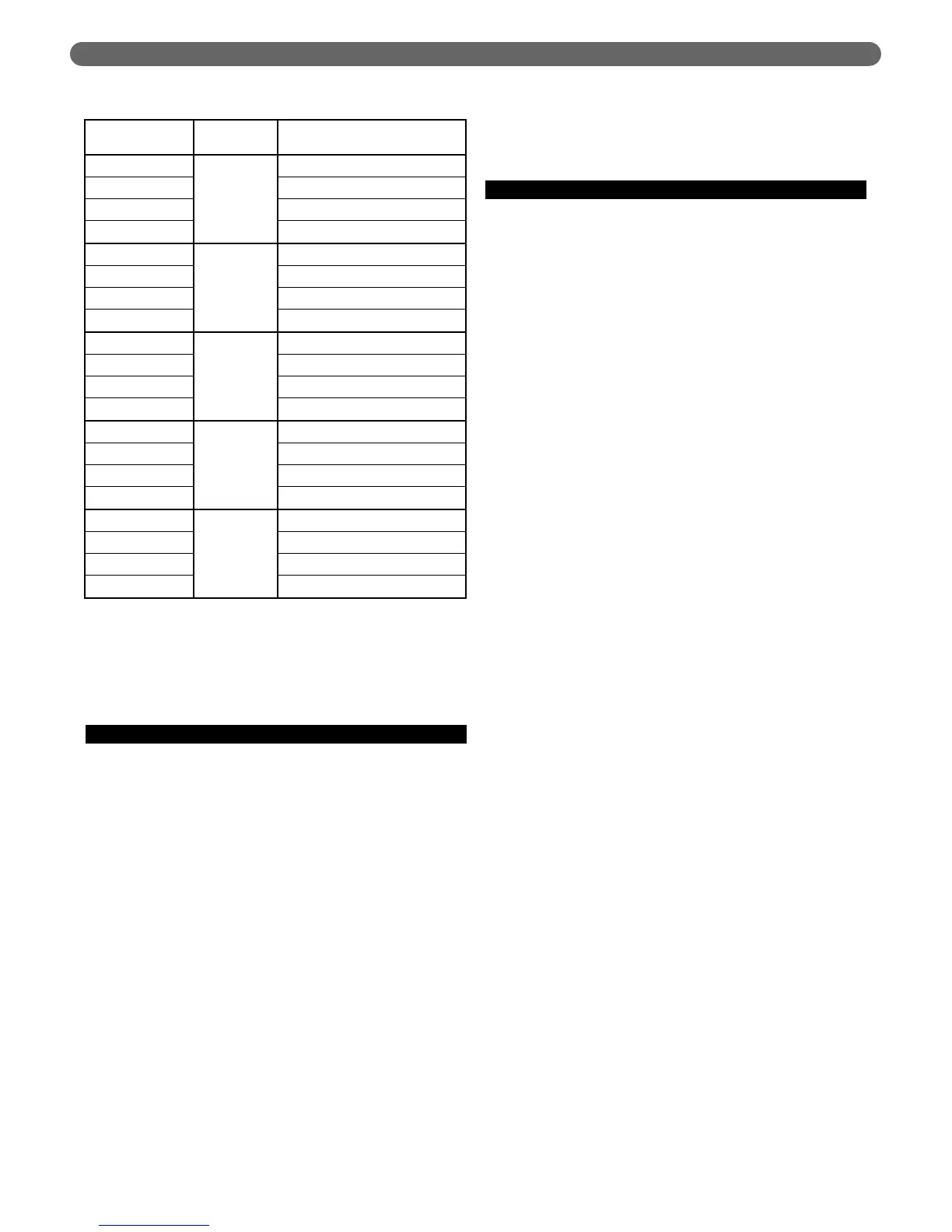
Table 4.5: PFC-460 Circulator Selection Chart
(General Pump – Primary Secondary)
Circulator
Manufacturer
Temp.
Difference Pump Model
Taco
20°F
1915/7.1" 1.5 HP
Grundfos
UPS32-160F Medium Speed
Bell & Gossett
N/A
Wilo
Top S 1.5 x 20 3 – 230V Max
Taco
25°F
2400-65
Grundfos
UPS26-150 SF Hi Speed
Bell & Gossett
N/A
Wilo
Top S 1.5 x 20 3 – 230V Max
Taco
30°F
2400-60
Grundfos
UPS26-150
Bell & Gossett
NRF-45 Speed 3
Wilo
Top S 1.5 x 20 1 – 115V Min
Taco
35°F
0013
Grundfos
UPS26-99 FC Hi Speed
Bell & Gossett
NRF-36 Speed 3
Wilo
Star 17 FX
Taco
40°F
0011
Grundfos
UPS26-99 FC High Speed
Bell & Gossett
NRF-45 Speed 1
Wilo
Star 17 FX
WATER PIPING AND CONTROLS