41
a. Last Lockout Error: The last lock menu allows the
user to view the reason for the last lockout. See
Table 10.2 for a list of locking errors and the
associated codes. Note that a value of #255
indicates that there are no lockout errors in the
control history. Also, note that the errors displayed
may have occurred during the factory fire test or
field commissioning of the equipment.
b. Last Blocking Error
: The last block screen allows the
user to view the reason for the last blocking error.
See Table 10.1 for a list of blocking errors and the
associated “E” codes. Note that a value of #255
indicates that there are no blocking errors in the
control history. Also, note that the errors displayed
may have occurred during the factory fire test or
during field commissioning of the equipment.
D. INSTALLER MENU
1. Menu Overview
The installer menu allows installing or service
contractors to view and/or make adjustments to the
permanent boiler settings based on the installation
configuration, desired operation and local codes. The
menu structure is shown in Figure 8.12.
To access the installer menu, press and hold the
“Menu” and “Select” key on the LCD display.
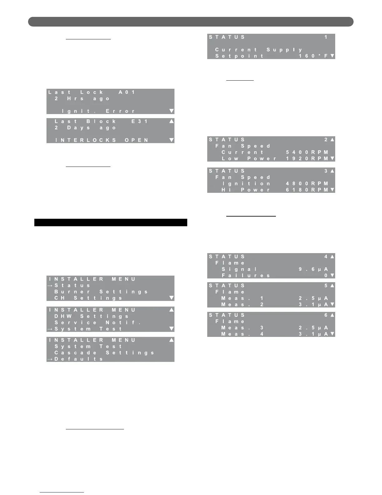
2. Status
The status menu is designed to monitor key parameters and
aids the installer or service contractor in determining if
there are problems with boiler operation.
a. Current Supply Setpoint
: The setpoint value will
change for DHW demands or CH demands
depending on the setpoint chosen for these modes
of operation. When outdoor reset modes are
selected, this value is the calculated target for the
system.
b. Fan Speeds
: Screens #2 & #3 display fan speed
information. The current fan speed will vary
during operation between the low power and high
power values. The Low Power, Ignition, and Hi
Power values are preset at the factory for a specific
model size. Table 12.3, in Section 12 of this
manual, shows the fan speed presets for each
model size. Note that these values may vary
slightly due to air setting changes.
c. Flame Measurements
: Screens #4, #5 & #6
display flame signal information. The first value,
Flame Signal, is the current flame rectification signal
in micro amps (µA). The minimum value for this
signal that will allow the burner to continue running
is 2.8 µA the maximum value for this is 10 µA.
The next value, Flame Failures, is the number of
times the burner has dropped out due to flame
failure. Several flame failures may have occurred
during the factory firetests and installation. If there
are a large number of flame failures showing on
this screen, contact your Peerless
®
Representative.
On Screens #5 and #6, the Flame Measurement
values 1-4 are logged in the last two seconds of
the most recent ignition sequence in 1/2 second
intervals. This helps service contractors to
diagnose ignition issues.
Figure 8.11: Messages – Last Errors
Figure 8.12: Installer Menu
Figure 8.13: Status – Supply Setpoint
Figure 8.14: Status – Fan Speeds
Figure 8.15: Status – Flame Signal
BOILER CONTROL: OPERATION