ECP200 BASE 2/4
Page 7
USE AND MAINTENANCE MANUAL
Rev. 01-09
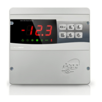
INSTALLING THE UNIT
Fig. 1: Undo the 4 screws on the front of the panel.
Fig. 2: Use the three existing holes to fix the box back panel
to the wall: use three screws of a length suitable for the
thickness of the wall to which the panel will be attached. Fit a
rubber washer (supplied) between each screw and the box
backing.
Make all the electrical connections as illustrated in the diagram for the corresponding
model (see relative table in APPENDICES).
To effect correct electrical connection and maintain the protection rating, use
appropriate wire/raceway grips to ensure a good seal.
Route the wiring inside the unit in as tidy a fashion as possible: be especially careful to keep power
wires away from signal wires. Use clips to hold wires in place.
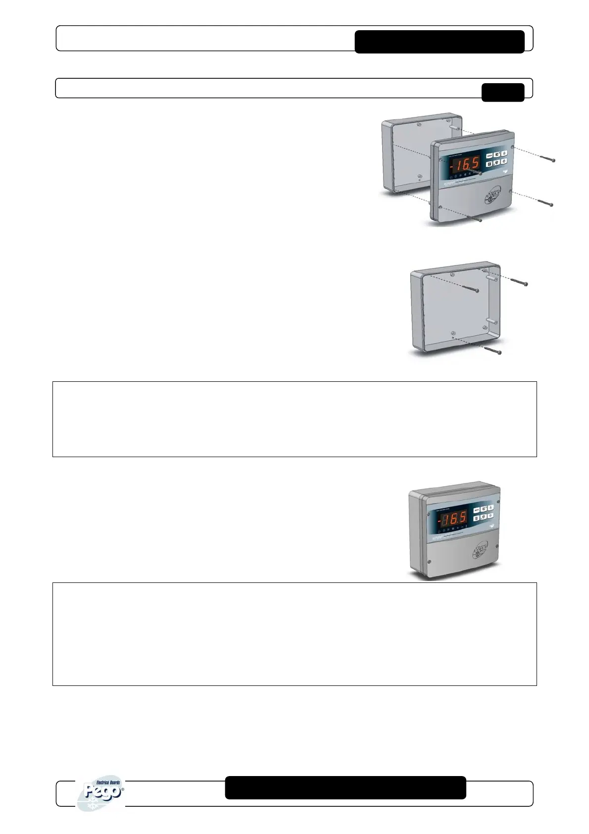
Fig. 3: close the front panel, making sure that all the wires are
inside the box and that the box seal sits in its seat properly.
Tighten the front panel using the 4 screws, making sure the O-rings
on the head of each screw are used.
Power up the panel and carry out thorough reading/programming of
all the parameters.
Be careful not to over-tighten the closure screws as this could warp the box and
compromise proper operation of the membrane-type keypad.
Install short-circuit overload safety devices on all the power cables connected to the
ECP200 controller so as to prevent damage to the device. Work and/or maintenance
must ONLY be carried out on the unit after disconnecting the panel from the power supply and
from any inductive/power loads: doing so allows the worker to do his job safely.
CHAP. 2 - Installation
 Loading...