ECP202 EXPERT + BASE
Page 8
USE AND MAINTENANCE MANUAL
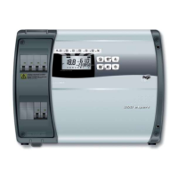
Fig. 6: Use the three existing holes to fix the
box back panel to the wall: use three
screws of a length suitable for the
thickness of the wall to which the
panel will be attached. Fit a rubber
washer (supplied) between each
screw and the box backing.
Fig. 7: Hook the frontal panel back up to the
lower part of the box by inserting the
two hinges in their seats and, bending
them, rotate downwards 180° to gain
access to the electronic board.
Make all electrical connections according to diagram A2.
To carry out the electrical connections reliably and maintain the degree of protection of the box, we
recommend using suitable cable glands and / or pipe clamps to tightly seal all the wiring.
It is advisable to distribute the cables within the panel as neatly as possible. In particular, keep the
power cables away from the signal cables. Use any sealing strips.
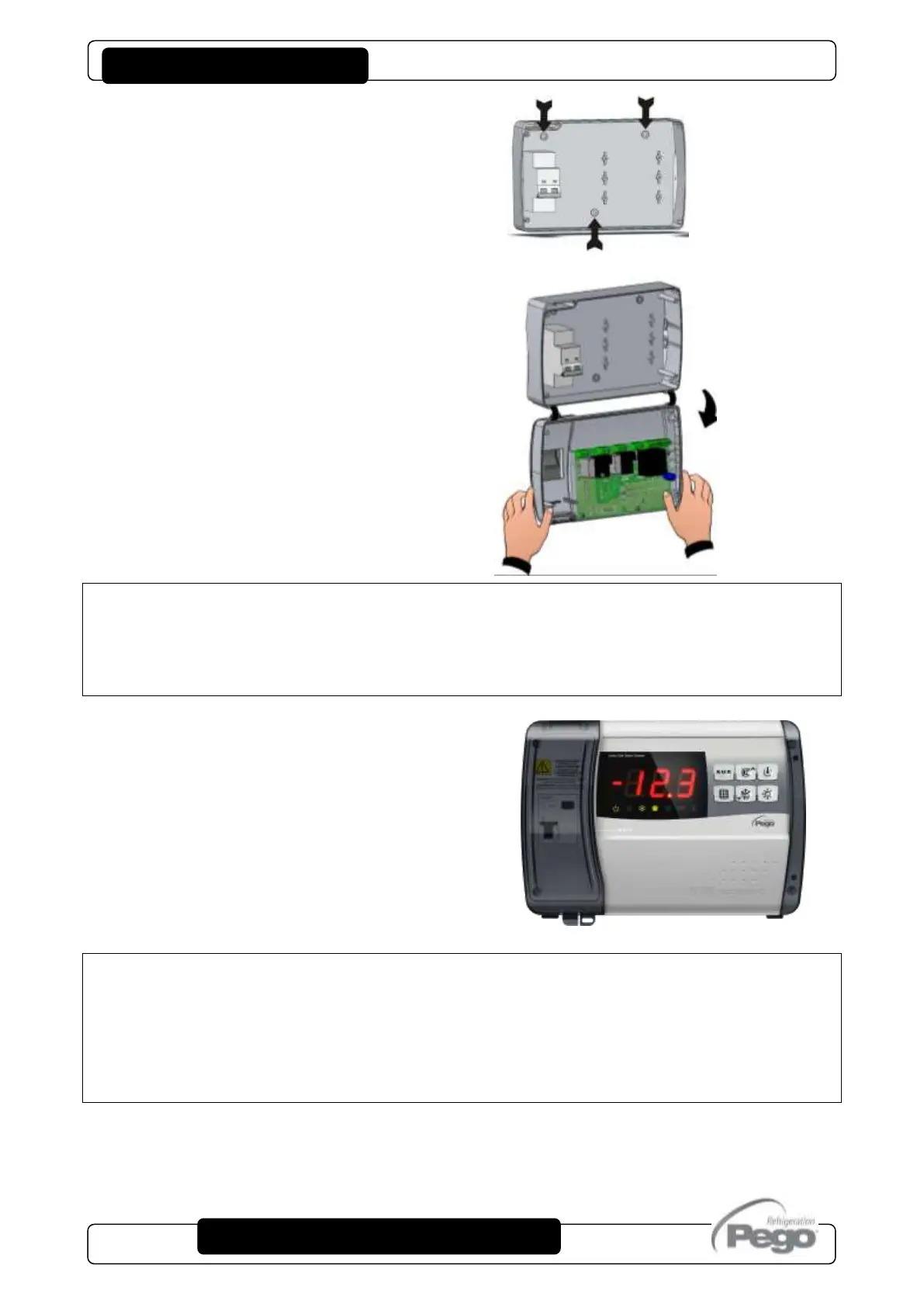
Fig. 8: Close the front panel, making sure that
all the wires are inside the box and that
the box seal sits in its seat properly.
Tighten the front panel using the 4
screws.
Give power supply to the panel and carry
out a scrupulous reading / programming
of all the parameters set.
Be careful not to over-tighten the closing screws as they could cause deformation of
the box and alter the correct operation and tactile effect of the panel keyboard.
On all loads connected to the ECP202 EXPERT + BASE electronic controller, install
overcurrent protection devices for short-circuits, to avoid damaging the device. Every
operation and / or maintenance operation must be carried out by disconnecting the panel from the
power supply and from all the possible inductive and power loads to which it is connected; this to
guarantee the maximum safety condition for the operator.

 Loading...