39 06/218390-017A
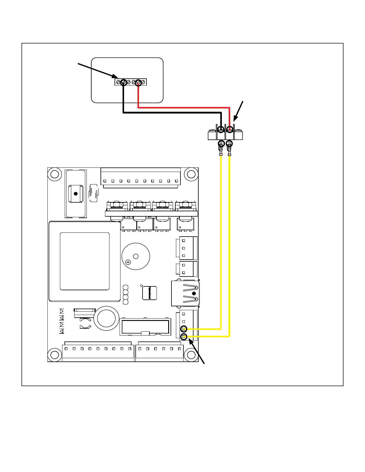
THERMOSTAT TROUBLESHOOTING
BLACK
WHITE
PURPLE
PURPLE
BLUE
BLUE
WHITE
RED
BLACK
BLACK
SIGNAL
GND
THERMOSTAT BLOCK
G C Y R RcW
DIGITAL THERMOSTAT
WHITE
RED
CONTINUITY
TEST POINTS
CONTINUITY
TEST POINTS
CONTINUITY
TEST POINTS
THERMOSTAT CIRCUIT SPECS:
5 VDC
Unplug the appliance. Set
Multimeter to resistance (Ω).
Touch the two probes to the
two ends of th white, red
and both yellow wires/ The
multimeter should show less
than 0.1 Ω if the connections
are good. If the meter shows
“Max” or any value above
0.1 Ω check and replace wire
connections.
 Loading...