Cyclone Universal & Cyclone Universal FX - User Manual 12
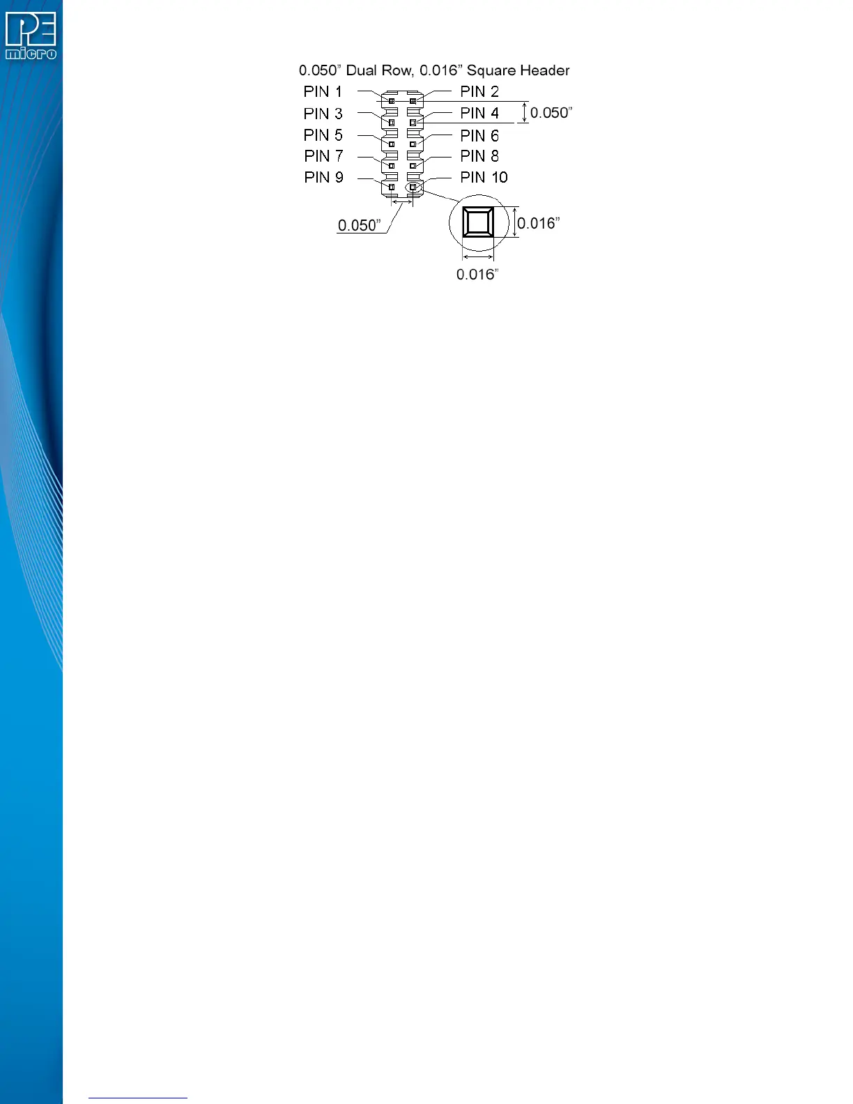
Figure 3-7: Mini 10-Pin and Mini 20-Pin Keyed Header Dimensions
3.19 PORT A: 10-Pin Keyed Mini Connector (Kinetis, S32 (ARM), other P&E-Supported ARM
devices)
The Cyclone provides a keyed 10-pin 0.050-inch pitch double row connector for ARM targets. The
location of the this header is indicated as PORT A in Figure 3-5. The 10-pin keyed mini connector
pin definitions for JTAG mode are as follows:
10-Pin Keyed Mini Connector JTAG Mode Pin Assignments
PIN 1 - TVCC TMS - PIN 2
PIN 3 - GND TCK - PIN 4
PIN 5 - GND TDO - PIN 6
PIN 7 - NC TDI - PIN 8
PIN 9 - NC RESET - PIN 10
The Cyclone Universal and Cyclone Universal FX also support SWD Mode. This replaces the
JTAG connection with a clock and single bi-directional data pin.
10-Pin Keyed Mini Connector SWD Mode Pin Assignments
PIN 1 - TVCC TMS/SWDIO - PIN 2
PIN 3 - GND TCK/SWCLK - PIN 4
PIN 5 - GND NC - PIN 6
PIN 7 - NC NC - PIN 8
PIN 9 - NC RESET - PIN 10
SWD Mode is selected from the “Communication Mode” drop-down box in the Cyclone Image
Creation Utility:
 Loading...