Cyclone Universal & Cyclone Universal FX - User Manual 14
PIN 13 - NC NC - PIN 14
PIN 15 - GND NC - PIN 16
PIN 17 - GND NC - PIN 18
PIN 19 - GND NC - PIN 20
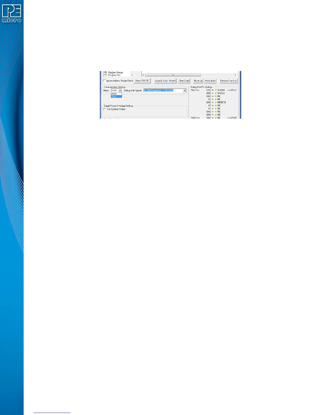
SWD Mode is selected from the “Communication Mode” drop-down box in the Cyclone Image
Creation Utility:
Figure 3-9: Communications Mode Selection
3.21 PORT C: 14-Pin Debug Connector (Qorivva, SPC5, DSC, S32 (Power))
The Cyclone provides a standard 14-pin 0.100-inch pitch dual row 0.025-inch square header for
Qorivva (MPC5xxx), DSC (MC56F8xxx), S32R, or STMicroelectronics’ SPC5 targets. The location
of the this header is indicated as PORT C in Figure 3-5.
Qorivva, SPC5, or S32 (Power) Pinout
TDI 12GND
TDO 34GND
TCK 56GND
NC 78NC
RESET 910TMS
VDDE7 11 12 GND
RDY 13 14 JCOMP
DSC Pinout
TDI 12GND
TDO 34GND
TCK 56GND
NC 78NC/KEY
RESET 910TMS
VDD 11 12 GND
NC 13 14 TRST
3.21.1 BERG14-to-MICTOR38 Optional Connector
P&E offers a 14-pin BERG to 38-pin MICTOR adapter, sold separately, that may be used on Port C
of the Cyclone Universal and Cyclone Universal FX. The P&E part number is BERG14-TO-
MICTOR38.