2
FOUNDATION. The foundation for your pump must be
sufficiently rigid to absorb any vibration and stress encountered
during pump operation. A raised foundation of concrete is
preferable for most floor mounted pumps. The raised foundation
assures a satisfactory base, protects against flooding, simplifies
moisture drainage, and facilitates keeping the area clean.
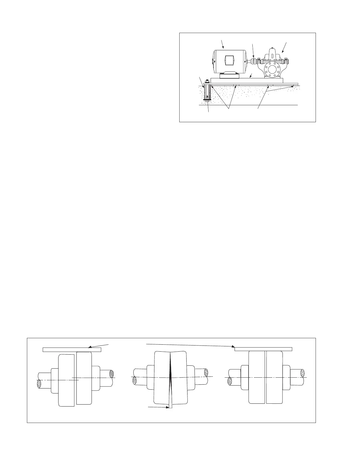
Your pump should be firmly bolted to the foundation, whether it
is a raised concrete base, steelwork wall, or structural member.
The mounting bolts or lag screws should be accurately located
per the applicable Aurora
®
dimension sheet. Refer to Fig. 1.
LEVELING THE PUMP. Leveling the pump will require
enough shims to support the baseplate near the foundation bolts
and at any points of the baseplate carrying a substantial weight
load. The shims should be large enough to allow a gap of 3/4"
to 1-1/2" between the baseplate and foundation for grouting.
INITIAL ALIGNMENT OF THE FLEXIBLE COUPLING.
The pump and driver were accurately aligned at the factory.
However, it is impossible to maintain this alignment during
shipping and handling. Therefore it will be necessary for you
to realign the pump and driver. Flexible couplings are not
universal joints. They should not be used to compensate for
misalignment of the pump and motor shafts. Their function is to
transmit power from the driver to the pump while compensating
for thermal expansion and shaft end movement. The coupling
faces should be far enough apart so that they do not make
contact when the motor shaft is forced to the limit of the bearing
clearance toward the pump shaft.
In order to properly align the coupling, you will need a taper
gauge or set of feeler gauges and a straight edge.
There are two types of misalignment encountered with flexible
couplings: angular misalignment, in which the shafts are not
parallel, and parallel misalignment where the shafts are parallel
but not on the same axis.
To check angular alignment, insert a feeler gauge or taper gauge
at any four places 90° apart around the coupling halves. Insert
shims under the driver feet until the same reading is obtained
at all four checkpoints. The pump and driver will then be in
angular alignment.
To check parallel alignment, a straight edge should be held
against the edges of the coupling halves at any four places 90°
apart around the coupling. The straight edge should be parallel
to the pump and driver shafts at all times. Insert shims until
the straight edge lies flat against both coupling halves at all
four checkpoints. The pump and driver will then be in proper
parallel alignment. Refer to Fig. 2.
SUCTION PIPING. The suction piping should be short, but no
less than ten pipe diameters in length, and direct with as few
elbows and fittings as possible to keep head loss, from friction,
at a minimum. However, the suction pipe should provide a
minimum uninterrupted length, equal to ten pipe diameters, to
the pump suction flange. A horizontal suction line should have a
gradual rise to the pump and pass under any interfering piping.
The suction pipe diameter should be at least the same diameter
as the suction nozzle on the pump, and preferably larger. Use
of a smaller diameter pipe will result in loss of head due to
friction. All joints must be tight to maintain prime on the pump.
REDUCERS. Eccentric reducers should be installed directly at
the suction nozzle, with the taper at the bottom to prevent air
pockets from forming. Straight taper reducers should never be
used in a horizontal suction line because of the air pocket that is
formed at the leg of the reducer and the pipe. Refer to Fig. 3.
ELBOWS. Long radius elbows should be used in place of
standard elbows wherever possible because of their superior
flow characteristics. For instance, head loss in a standard four
inch elbow is equivalent to the head loss in a piece of pipe
11 feet long, while the head loss in a long radius elbow is
approximately half as much. Elbows should not be used at the
suction nozzle, but if it is unavoidable, they should be installed
in a vertical position. Elbows installed in any position at the
suction nozzle have a tendency to distribute the liquid unevenly
in the impeller chamber, causing a reduction in capacity, and
creating an undesirable thrust condition. Refer to Fig. 4.
SHIMS
SHIMS
FOUNDATION BOLT
GROUTING CLEARANCE
PIPE
DRIVER
FLEXIBLE COUPLING
PUMP
BASEPLATE
CONCRETE
FOUNDATION
Figure 1. Foundation for frame mounted pumps.
STRAIGHT EDGE
PARALLEL MISALIGNMENT
ANGULAR MISALIGNMENT
WEDGE OR
THICKNESS GAUGE
PERFECT ALIGNMENT
Figure 2. Flexible coupling alignment.
MODELS 411-412-413