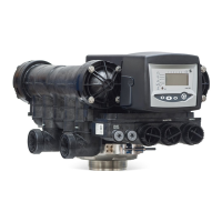
Installer manual Autotrol Magnum 293 - 298 Logix 742-762 - Description
Ref. MKT-IM-012 / D - 03.02.2022 23 / 110
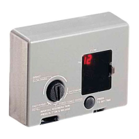
3.6.4.3 Breakaway switch cam instructions
Based on the system requirements and the external devices used, determine the program timing,
ie., when the external devices need to operate, either open or close.
Typical external devices would be solenoids, solenoid operated diaphragm valves, relays, and
chemical feed pumps. Using the instructions below, sections can be removed from the breakaway
cam to allow signalling during the desired cycles. One cam can be used to signal multiple non-
contiguous cycles.
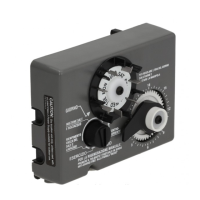
1. Determine which breakaway cam sections need to be removed using the chart below. In
order to assure that switch deactivation occurs, at least three sections must be removed
from the breakaway switch cam.
The sections should be removed in a clockwise fashion, starting with the first number and
ending with the second (see picture 1). Utilizing the timing chart on the back, determine if the
switch arm should be riding on the cam [actuated] or not [relaxed].
Tip
Remember that the switch operates either normally open or normally closed
depending upon how it is wired.
2. Using diagonal cutters or a razor knife, cut through the cam on either side of the section you
wish to remove. The breakaway cam section should be trimmed to the edge of the section
which is to remain on the breakaway cam, see picture 2. Cut the outside ring first, then at the
score line on the bottom of each section near the center ring.
Tip
When starting to remove sections, start two or three sections before the section
required.
Then remove one section at a time until the required section is reached. This procedure
eliminates the potential of damage to usable sections.
3. When all of the desired sections have been removed, add the breakaway switch cam(s) to the
camshaft after the B1/B2 pilot cam.
The switch cam can be installed onto the camshaft in only one direction. The numbers on the
breakaway switch cam should face the controller.
4. Replace the standard pilot cams in the proper order and reinstall the camshaft onto the
control valve. Refer to Motor replacement [
→
Page79] for instructions on the removal and
replacement of the camshaft assembly.
Cycle Section numbers
Service (C0) 19, 20, 21, 22, 23, 24, 25
Backwash (C1) 26, 27, 28, 29, 30, 31, 32
Brine (C2) 33, 34, 35, 36, 1
Slow rinse (C3) 2, 3, 4, 5, 6, 7, 8, 9, 10
Fast rinse (C5) 11, 12, 13, 14
Refill (C8) 15, 16, 17, 18
 Loading...