
T
Tracy SmithAug 21, 2025
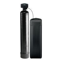
Why is my Pentair Water Dispenser using too much salt?
- EEmily TaylorAug 21, 2025
Your Pentair Water Dispenser might be using too much salt due to an improper salt setting. Check the salt usage and salt setting. It can also be caused by excessive water in the brine tank. In this case, you should inspect the brine tank.