-4-
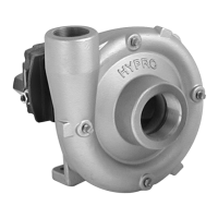
mation. Read all instructions and general safety information
before attempting to install or operate the pump.
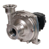
Drive Source Installation for the 9940-9750NRL Pedestal Mount Pump
Belt/Pulley Drive Installation
1
To gure proper diameter of pump pulley, multiply motor/engine
rpm by the diameter of the motor/engine pulley and divide that
gure by the desired pump speed.
Pump = Motor RPM x Motor Pulley Size
Pulley Size Desired Pump Speed
Refer to the pump performance charts to determine the desired
speed to obtain the desired maximum ow.
Push the belt
midway between
the pulleys, check
the deection (d)
and adjust:
d = 0.016 x L
2
Mounting Belts and Pulleys
Mount pulleys as close to the pump and motor engine shaft
bearings as possible. Check the alignment with a straight edge
as shown in Fig. 1. Make sure that the belt has proper tension.
(Too much tension will cause bearing wear; too little will cause
slippage.) See Fig. 2. Check with belt and pulley sources for
specic recommendation.
Direct Drive — Flexible Coupling
For direct driving of Hypro centrifugal pumps with exible
couplings, make sure that the speed (rpm) of the gas engine
or electric motor is within the maximum rated rpm of your
pump. Make sure that shaft rotation is correct between the
pump and the motor or gas engine (See Fig. 3).
4. Re-position the pump, sliding the coupling halves to-
gether. NOTE: No end thrust should be applied to the
pump when the coupling is connected.
5. Tighten the pump mounting and then the setscrews on
each coupling.
1. Mount the motor or engine into position on the base.
2. Line-up the pump shaft with the straight edge as shown
in Fig. 3 to assure they are aligned. Shim the pump if
necessary to match the shaft height of the engine or
motor. The shaft ends should not touch.
3. Mark the exact position of the pump on the base —
remove and install the coupling halves on both shafts.
Place the coupling center disc into one of the coupling
halves.
3
Pump
Motor or Engine
Regular Flex Coupling
Straight Edge
All electrical wiring should meet state and local ordinances.
Improper wiring may not only be a safety hazard but may
permanently damage the motor and/or pump!
1. Check that supply voltages match the motor's requirements.
2. Check the motor wiring and connect according to the mo-
tor instructions for matching supply voltage. Be sure of
proper rotation! Improper rotation will severely damage
the pump and void the warranty.
3. The power cord should be protected by conduit or by cable
and be of the proper gauge. It should be no longer than
necessary.
4. The power should be drawn directly from a box with circuit
breaker protection or with a fused disconnect switch.
5. Always switch off the power before repairing or servicing
the pump and/or motor.
6. Check for the proper rotation of three phase motors.
Electrical Hook-up
This manual covers the installation of the basic drive con-
guration for the 9940-9750NRL centrifugal pump. Consult
the manufacturer of your motor or engine for additional infor-
 Loading...