MASTERTEMP
™
Pool and Spa Heater Installation and User’s Guide P/N 475106 Rev. A 2/2014
10 | Section
Pool
Main
Drain
Spa
From Pool
3-Way
Valve
3-Way
Valve
3-Way
Valve
Chlorinator
Heater
Pump
Check Valve
Filter
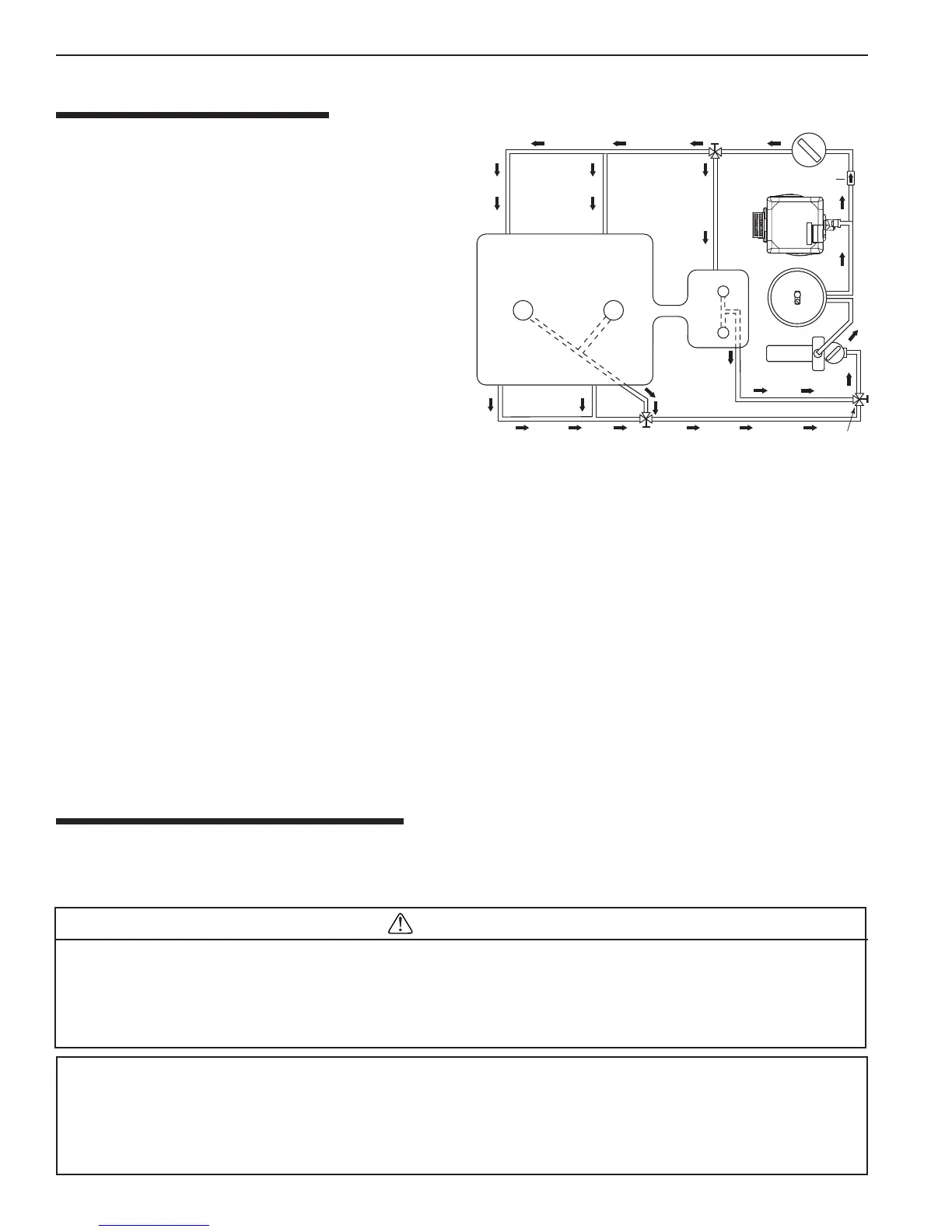
WATER CONNECTIONS
The heater requires proper water flow and pressure for its
operation. See Figure 12 for the recommended installation.
The filter pump dischar
ges to the filter, the filter discharges to
the heater, and the heater discharges directly to the pool or
spa.
A manual bypass valve should be installed across the heater
when the pump flow exceeds 454 LPM (120 GPM). See
“WATER FLOW RATE” on page 9 - Table 1 for setting of
the manual by-pass valve.
Make sure that the outlet plumbing from the heater contains
no shut-off valves or other flow restrictions that could prevent
flow through the heater (except for below pool as noted below
,
or winterizing valves where needed). To switch flow between
the pool and spa, use a diverter valve. Do not use any valve
that can shut off the flow. Do not use a shut-off valve to
isolate the heater unless it is below the level of the pool or spa.
Install the chemical feeder downstream of the heater. Install
a chemical resistant one-way check valve between the heater and the chemical feeder to prevent back-siphoning through
the heater when the pump is off.
NOTICE: If the heater is plumbed in backwards, it will cycle continuously. Make sure piping from filter is not reversed
when installing heater.
Connect the heater directly to 5 cm PVC pipe, using the integral unions provided. Heat sinks are not required. The low
thermal mass of the heater will prevent overheating of the piping connected to the pump even if the heater shuts down
unexpectedly. Occasionally a two-speed pump will not develop enough pressure on the low speed to operate the heater.
In this case, run the pump at high speed only to operate the heater. If this does not solve the problem, do not try to run the
heater. Instead, correct the installation.
Do not operate the heater while an automatic pool cleaner is also operating. If the circulation pump suction is plugged (for
example by leaves), there may not be adequate flow to the heater. Do not rely on the pressure switch in this case.
If British Standard Codes of Practice require the installation of a pressure relief valve (PRV), see page 36 for
“PRESSURE RELIEF
VALVE INSTRUCTIONS”.
BELOW POOL INSTALLATION
If the heater is below water level, the pressure switch must be adjusted. This adjustment must be done by a qualified
service technician.
See following CAUTION before installation.
CAUTION
BELOW OR ABOVE POOL INSTALLATION
The water pressure switch is set in the factory at 21 kPa (± 5 kPa), (3 ± 0.7 psi). This setting is for a heater installed at
pool level. If the heater is to be installed more than 0.3 m above or below, the water pressure switch must be adjusted
by a qualified service technician. See page 32, Figure 22.
FLOW SWITCH
If the heater is installed more than 1.5 m above the pool or more than 1.2 m below the pool level, you will be beyond
the limits of the pressure switch and a flow switch must be installed. Locate and install the flow switch externally on
the outlet piping from the heater, as close as possible to the heater. Connect the flow switch wires in place of the
water pressure switch wires.
Figure 12.
2. Installation