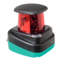
2-D LiDAR Sensor
Product Description
2020-05
13
Interface:
There is a 4-pin M12 socket on the rear of the housing for connecting the Ethernet
interface. The following diagram shows the pinout:
Figure 3.3 Ethernet connection layout
The connector housing is located on the shield.
3.7 Scope of Delivery
The scope of delivery includes:
■ R2000
■ Quick start guide
■ Protective cover
■ 3 x socket cap screws, M5 x 10
■ 3 x washers, size 5
1 TD+
2 RD+
3 TD-
4 RD-
Note
Installation Instructions for North America
If a connection is made to the M12 multi-pin connector, the product shall be used
with a UL-listed cable/connector (CYJV) assembly rated minimum 30 VDC,
minimum 1.0 A, in the final installation for power supply.
 Loading...