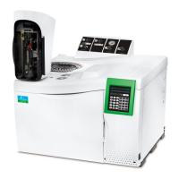
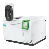
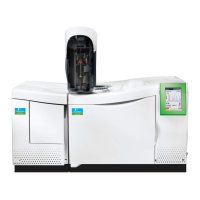
Clarus 500 GC Installation Guide
69
Common Injector/Detector Gas Connections
Figures 13 through 21 shows how gases are connected to the Clarus 500 GC in several
common injector/detector configurations. Note that the strain relief, which is required on all
gas lines, is not shown in these figures.
WARNING
Position incoming gas lines away from the oven exhaust duct so that the hot
exhaust will not blow directly on the gas lines.
CAUTION
Thoroughly purge the incoming gas lines before measuring and adjusting the
gases. This is especially important when using hydrogen gas.
NOTE: For Clarus 500 GC’s that have a combination of both PPC and manual pneumatics, set the
detector gas delivery pressure between 60 and 90 psig and install the fixed 30-psig stainless
steel diaphragm regulator (P/N N610-1473), behind the Clarus 500 GC for the manual
pneumatics detector gases.
The manual pneumatics bulkhead always contains Swagelok nuts in all six locations whether
or not there is an injector or a detector connected to this bulkhead. The PPC modules will be
installed only if your Clarus 500 GC has been configured with PPC for an injector and/or
detector.
The Clarus 500 GC can be configured as any of the following:
• All zones (injector/detector) as PPC.
• All zones as manual pneumatics.
 Loading...
