KENR6908 11
Troubleshooting Section
•
Diagnostic tests
•
Sensor calibration
•
Flash programm
ing
•
Set parameters
Table 2 lists the service tools that are required in
order to use Perkins EST.
Table 2
Service Tools for the Use of Perkins EST
Part
Number
Description
-
(1)
Personal Computer (PC)
-
(1)
Single user license for Perkins E ST
27610251
(2)
Compact Communication Adapter
27610164
(3)
TIPSS Communication Adapter
(1)
Refer to the P erkins E ngine Company Limited.
(2)
The 27610251 Compact Communication Adap ter is s uitable
for use on a serial port and a US B port only.
(3)
The 27 610164 TIPSS Communic ation A dapter is suitable for
use on a serial port and a parallel port only.
Note: For more information regarding the use of
PerkinsEST and the PC requirements for Perkins
EST, refer to the documentation that accompanies
your Perkins EST.
Connecting the Electronic Service Tool
and the Communi
cation A dapter
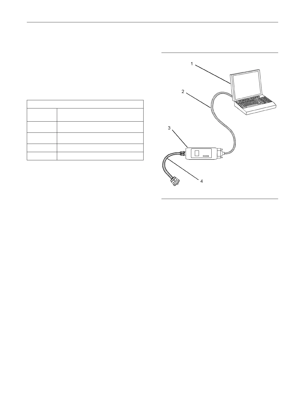
g01115382
Illustration 3
(1) P ersonal compu ter (PC)
(2) Adapter Cable
(3) Co mmunication A dapter
(4) Adapter Cable
Use the following procedure in order to connect the
electronic service tool to the communication adapter.
1. Turn the keysw itch to the OFF position. If the
keyswitch is not in the OFF position, the engine
may start.
2. Connect cable (2) between the “COMPUTER” end
of communication adapter (3) and the applicable
port on PC (1).
3. Connect adapter cable (4) between the “DATA
LINK” end of communication adapter (3) and the
diagnostic connector.
4. Move the keyswitch to the ON position. If the
electronic service tool and the communication
adapter do not communicate with the Electronic
Control Module (ECM), refer to Troubleshooting,
“Electronic Service Tool Will Not Communicate
With ECM”.
This document has been printed from SPI². Not for Resale