i05422613
Features and Controls
Battery Disconnect Switch
(If Equipped)
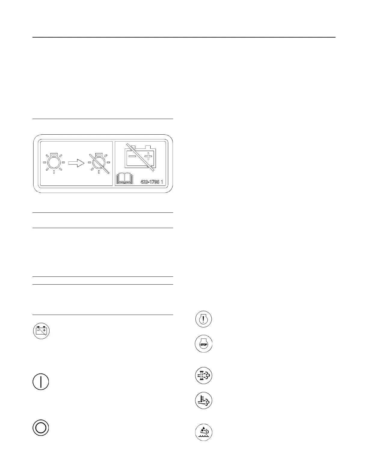
Illustration 33 g03422039
NOTICE
Do not turn off the battery disconnect switch until the
indicator lamp has turned off. If the switch is turned
off when the indicator lamp is illuminated the Diesel
Exhaust Fluid (DEF) system will not purge the DEF. If
the DEF does not purge, DEF could freeze and dam-
age the pump and lines.
NOTICE
Never move the battery disconnect switch to the OFF
position while the engine is operating. Serious dam-
age to the electrical system could result.
Battery Disconnect Switch – The battery
disconnect switch can be used in order
to disconnect the battery from the
engines electrical system. The key must be
inserted into the battery disconnect switch
before the battery disconnect switch can be
turned.
ON – To activate the electrical system,
insert the disconnect switch key and
turn the battery disconnect switch
clockwise. The battery disconnect switch must
be turned to the ON position before you start the
engine.
OFF – To deactivate the electrical
system, turn the battery disconnect
switch counterclockwise to the OFF
position.
The battery disconnect switch and the engine start
switch perform different functions. The entire
electrical system is disabled when you turn the
battery disconnect switch to the OFF position. The
battery remains connected to the electrical system
when you turn the engine start switch to the OFF
position.
Turn the battery disconnect switch to the OFF
position and remove the key when you service the
electrical system or any other engine components.
Turn the battery disconnect switch to the OFF
position and remove the disconnect switch key after
you operate the engine. This will prevent the battery
from being discharged. The following problems can
cause battery discharge:
• short circuits
• current draw via some components
• vandalism
i06163203
Monitoring System
The monitoring system is designed to alert the
operator to an immediate problem with any of the
engine systems that are monitored. The monitoring
system is also designed to alert the operator to an
impending problem with any of the engine systems
that are monitored. The monitoring system can be
accessed by the electronic service tool. For more
information on the electronic service tool, refer to
Troubleshooting , “Electronic Tools”.
Monitoring System Indicators
Engine Malfunction – This indicator
illuminates when there is a fault with the
engine or after treatment system.
Engine STOP – This indicator will
illuminate solid when a level 3 warning
fault has been detected by the
monitoring system.
Diesel Particulate Filter (DPF) – This
indicator will illuminate in order to show
that a regeneration is needed.
Regeneration Active – This indicator will
illuminate in order to show that a
regeneration is active and exhaust
temperatures are elevated.
Diesel Exhaust Fluid (DEF) Level – This
gauge shows the amount of DEF in the
DEF tank.
36
SEBU9071-06
Operation Section
Features and Controls