Test the Service Indicator
Service indicators are important instruments.
• Check for ease of resetting. The service indicator
should reset in less than three pushes.
• Check the movement of the service indicator core
when the engine is run at full load speed. The core
should latch approximately at the greatest vacuum
that is attained.
If the service indicator does not reset easily, or if the
core does not latch at the greatest vacuum, the
service indicator should be replaced. If the new
service indicator will not reset, the hole for the service
indicator may be plugged.
If necessary, replace the service indicator more
frequently in environments that are severely dusty.
Replace the service indicator annually regardless of
the operating conditions. Replace the service
indicator when the engine is overhauled, and
whenever major engine components are replaced.
Note: When a new service indicator is installed,
excessive force may crack the top of the service
indicator. Tighten the service indicator to a torque of
2 N·m (18 lb in).
i06759592
Engine Crankcase Breather -
Clean
NOTICE
Perform this maintenance with the engine stopped.
If the crankcase breather is not maintained regularly,
the crankcase breather will become plugged. A
plugged crankcase breather will cause excessive
crankcase pressure that may cause crankshaft seal
leakage.
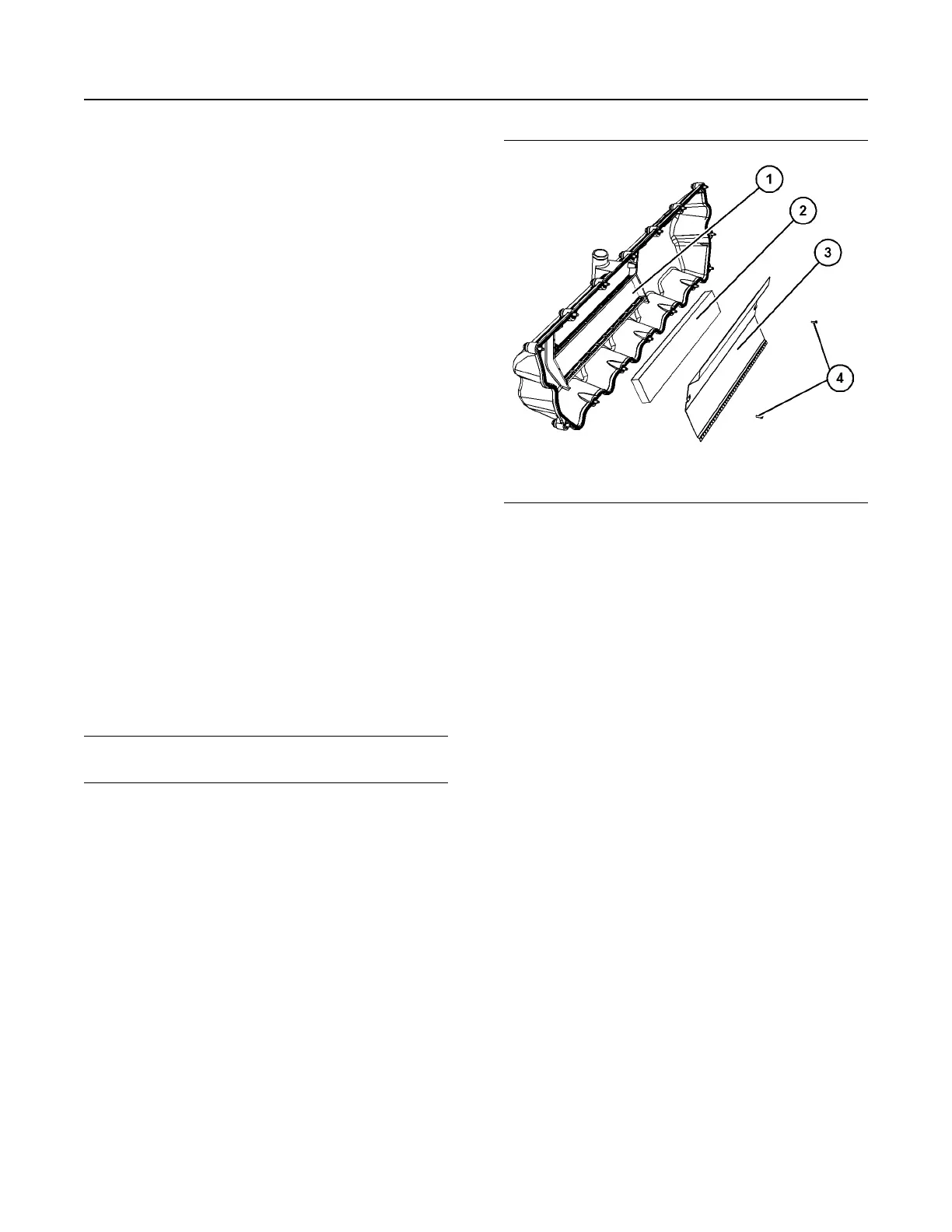
2806C Crankcase Breather
1. Remove the valve cover. Refer to Disassembly
and Assembly, “Valve Mechanism Cover -
Remove and Install”.
Illustration 54 g06109754
Typical example
2. Remove screws (4) from mechanism cover (1).
3. Remove cover plate (3) from mechanism cover (1)
and remove breather element (2).
4. Wash the breather element (2) in solvent that is
clean and nonflammable. Allow the breather to
dry. Before installation, check for damage to
element and replace element if necessary. Ensure
that the cover plate (3) is clean dry and free from
dirt.
5. Install breather element (2) into mechanism cover
(1). Install screws (4) into cover plate (3) and
install plate assembly to mechanism cover.
6. Tighten screws (4) to a torque of 1.7 N·m
(15 lb in).
7. Install the valve cover. Refer to Disassembly and
Assembly, “Valve Mechanism Cover - Remove
and Install”.
i07819538
Engine Mounts - Inspect
Note: The engine mounts may not have been
supplied by Perkins. Refer to the Original Equipment
Manufacturer (OEM) information for further details on
the engine mounts and the correct bolt torque.
Inspect the engine mounts for deterioration and for
correct bolt torque. Excessive engine vibration can
be caused by the following conditions:
90
SEBU9074-06
Maintenance Section
Engine Crankcase Breather - Clean