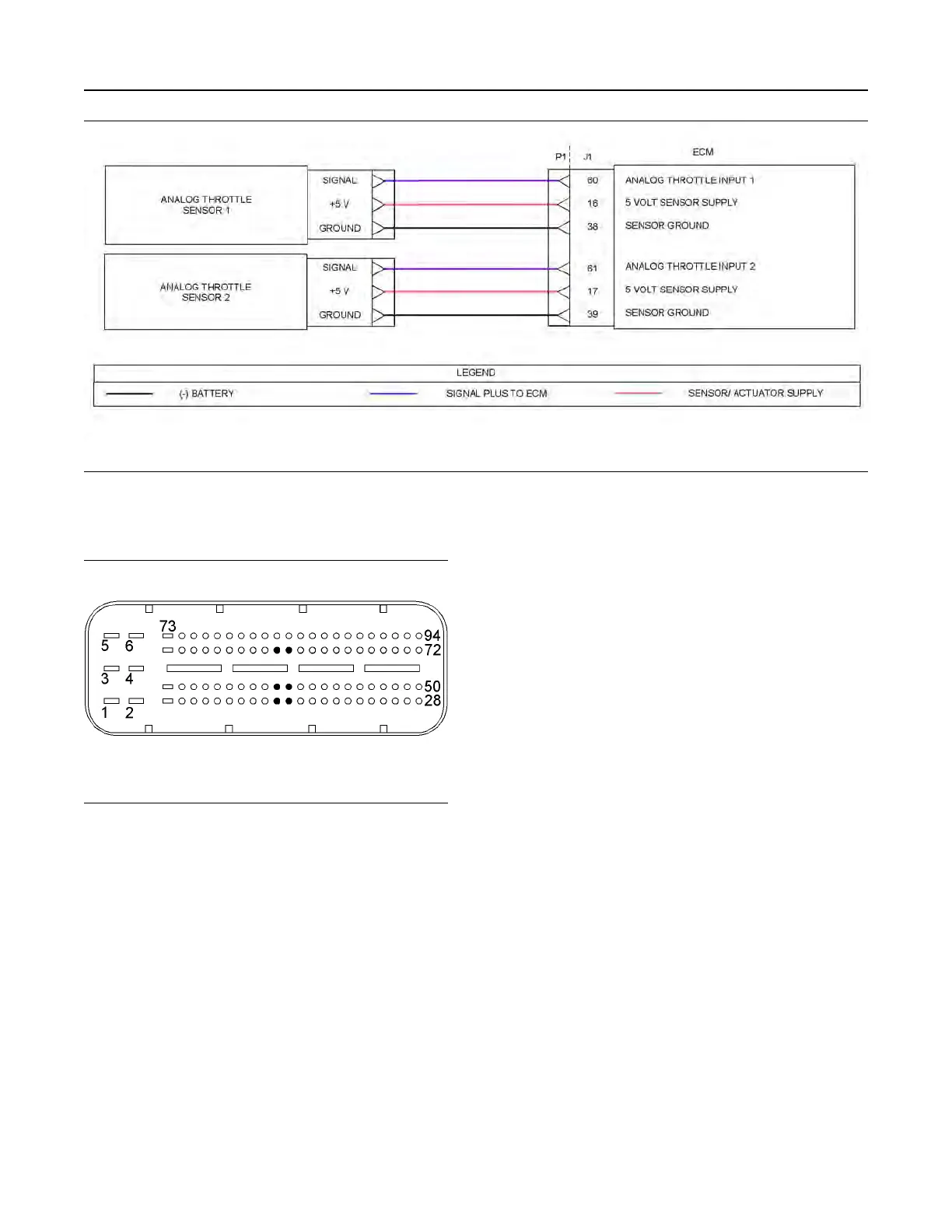
Illustration 63 g03733275
Schematic diagram for the throttle position sensors
Not all connectors are shown. Refer to the Electrical Schematic for the application.
Illustration 64 g02292314
View of the P1 pin locations for the analog throttle
position sensors
(16) 5 V supply (throttle 1)
(17) 5 V supply (throttle 2)
(38) Throttle 1 ground
(39) Throttle 2 ground
(60) Throttle 1 position
(61) Throttle 2 position
206 UENR0612
Circuit Tests
This document has been printed from SPI2. NOT FOR RESALE