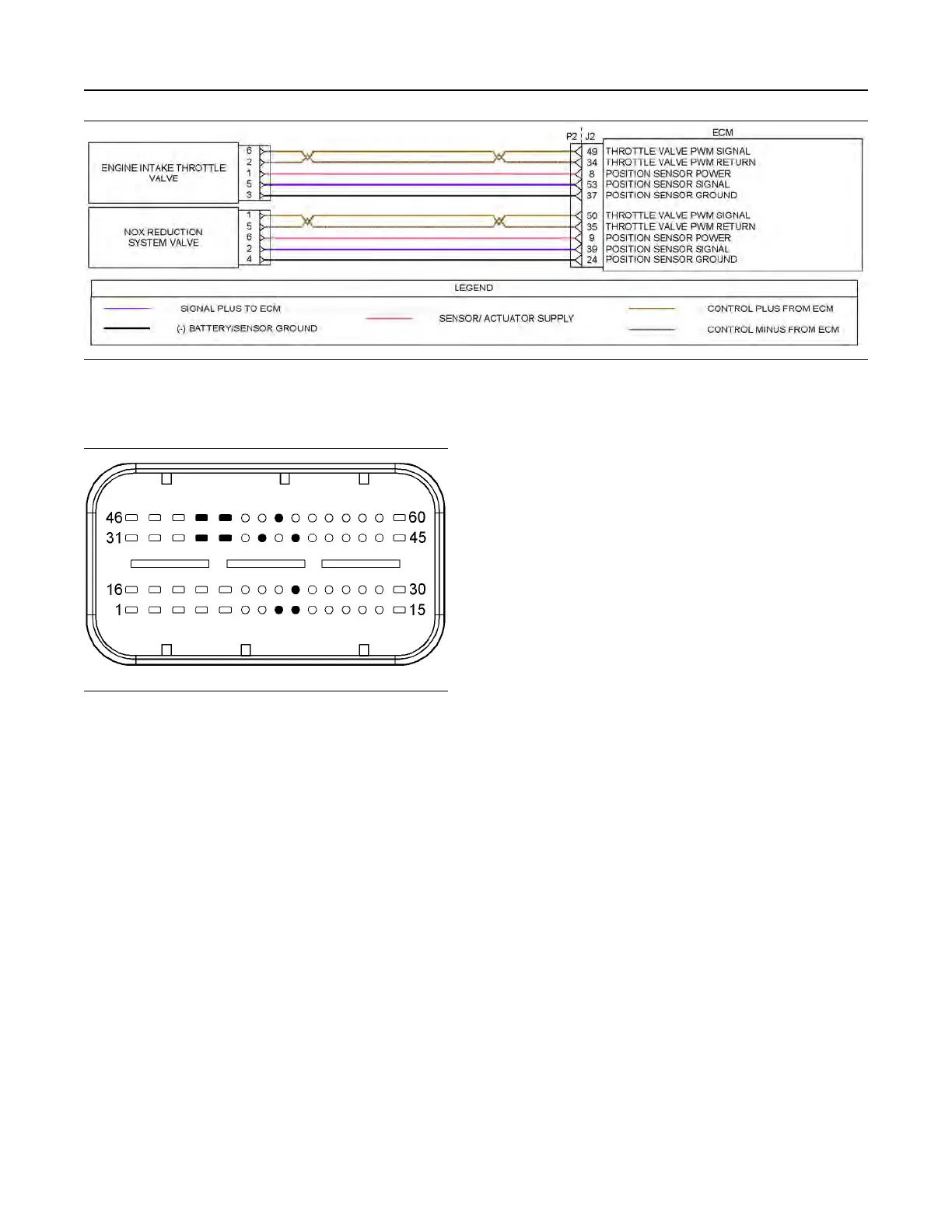
Illustration 76 g03636782
Schematic diagram for the valve position sensors
Not all connectors are shown. Refer to the appropriate Electrical Schematic.
Illustration 77 g03616849
Typical view of the pin locations on the J2 connector
for the valve position sensors.
(8) Intake throttle valve position sensor 5 VDC supply
(9) NRS valve position sensor 5 VDC supply
(24) NRS valve position sensor ground
(34) Intake throttle valve return
(35) NRS valve return
(37) Intake throttle valve position sensor ground
(39) NRS valve position sensor signal
(49) Intake throttle valve PWM signal
(50) NRS valve PWM signal
(53) Engine intake throttle valve position sensor signal
UENR0612 231
Circuit Tests
This document has been printed from SPI2. NOT FOR RESALE