F5 Corpus
Repairs - Chassis
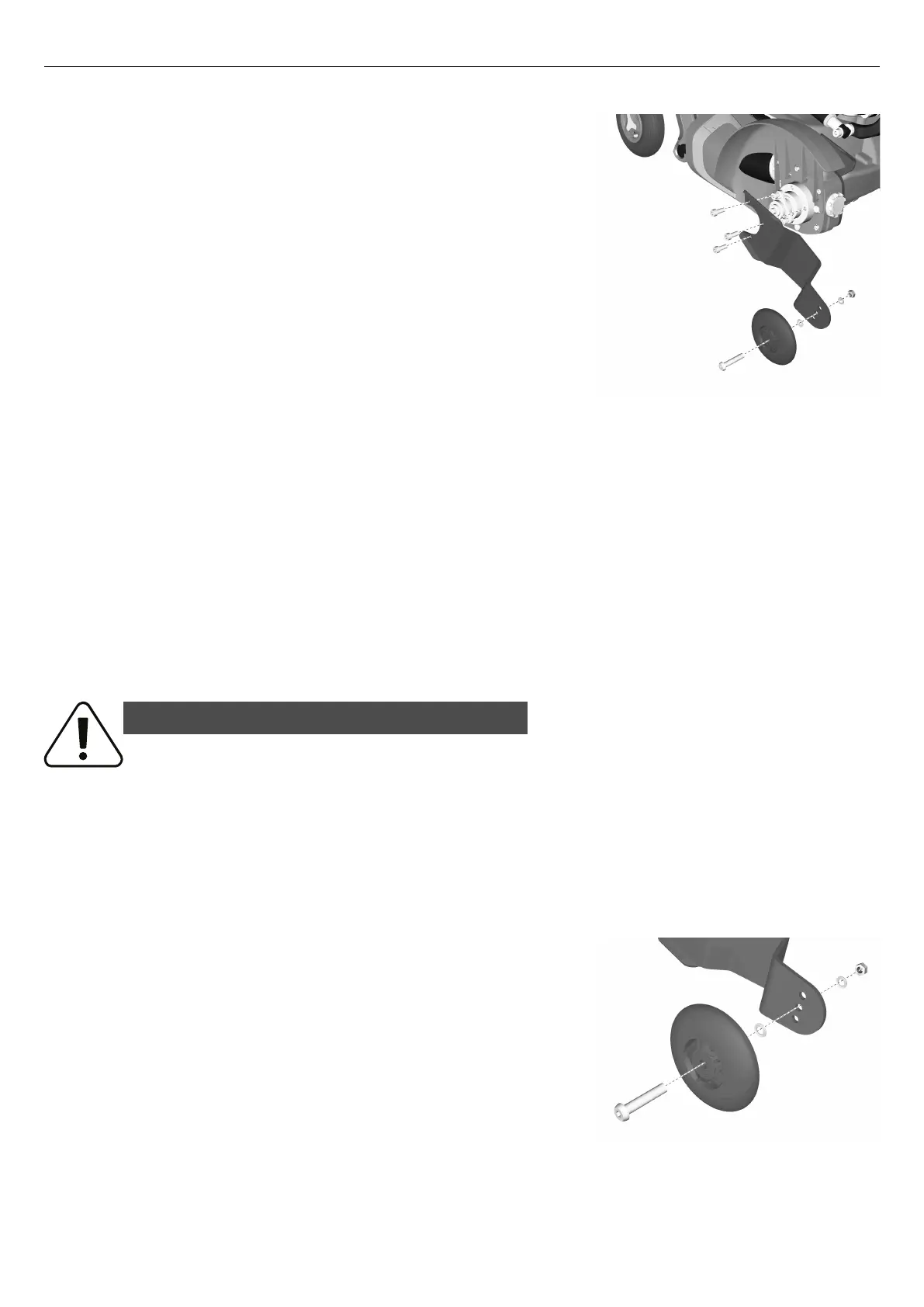
4.2.8.1 Removing support wheel unit
Figure 426. Support wheel unit.
1. Switch off the main power switch on the control panel.
2. Remove the drive wheel on the side in question.
3. Remove the three screws holding the support wheel unit.
4.2.8.2 Mounting support wheel unit
1. Assemble the support wheel unit using the three screws. Tighten the
screws using a torque wrench. Tightening torque: 17.7 lb.ft.
2. Assemble the drive wheel on the side in question.
4.2.9 Support wheels
For this task the following tools are necessary:
• 1 Allen key 5 mm.
• 1 Spanner 13 mm.
4.2.9.1 Removing support wheel
WARNING!
Risk of tipping - do not remove support wheels
If the wheelchair is fitted with support wheels they must remain installed to
reduce the risk of the wheelchair tipping forward due to speed or prevailing
circumstances. It is important to drive the wheelchair at a safe speed to reduce
the need for sudden stops that may cause the wheelchair to tip forward.
Always be aware of the seat position and how it might affect the stability of the
wheelchair on different surfaces even with support wheels.
Figure 427. Support wheel.
1. Switch off the main power switch on the control panel.
2. Remove the screw.
The user must weigh less than 220 lbs to drive without support
wheels.
The minimum seat depth is 17” to drive without support wheels.
142
 Loading...