F5 Corpus
Repairs - Chassis
4.2.9.2 Mounting support wheel
1. Switch off the main power switch on the control panel.
2. Fit the wheel with the screw, washer and nut in the desired position.
All users above 220 lbs must have support wheels and the wheels
should always be in the middle position.
All users above 245 lbs must have a minimum seat depth of 17”. See
fig. 427.
4.2.10 Magnetic wheel locks
For this task the following tools are necessary:
• 1 Allen key 3 mm.
• 1 Allen key 4 mm.
4.2.10.1 Removing magnetic wheel lock
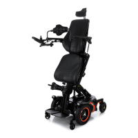
Figure 428. The connectors of the magnetic wheel
locks.
The wheelchair is equipped with a magnetic wheel locks on the left and
right drive motor. The magnetic wheel locks are both equipped with a
brake release lever which is used to manually release the brakes.
1. Switch off the main power switch on the control panel.
2. Remove the drive package covers. See
Removing drive motor cover
, Page 73.
3. Remove the chassis rear cover. See 4.2.1
Covers
, Page 67.
4. Disconnect the magnetic wheel lock at the connector on the cable.
Figure 429. Remove the cable cover.
5. Remove the cable cover by unscrewing the two screws.
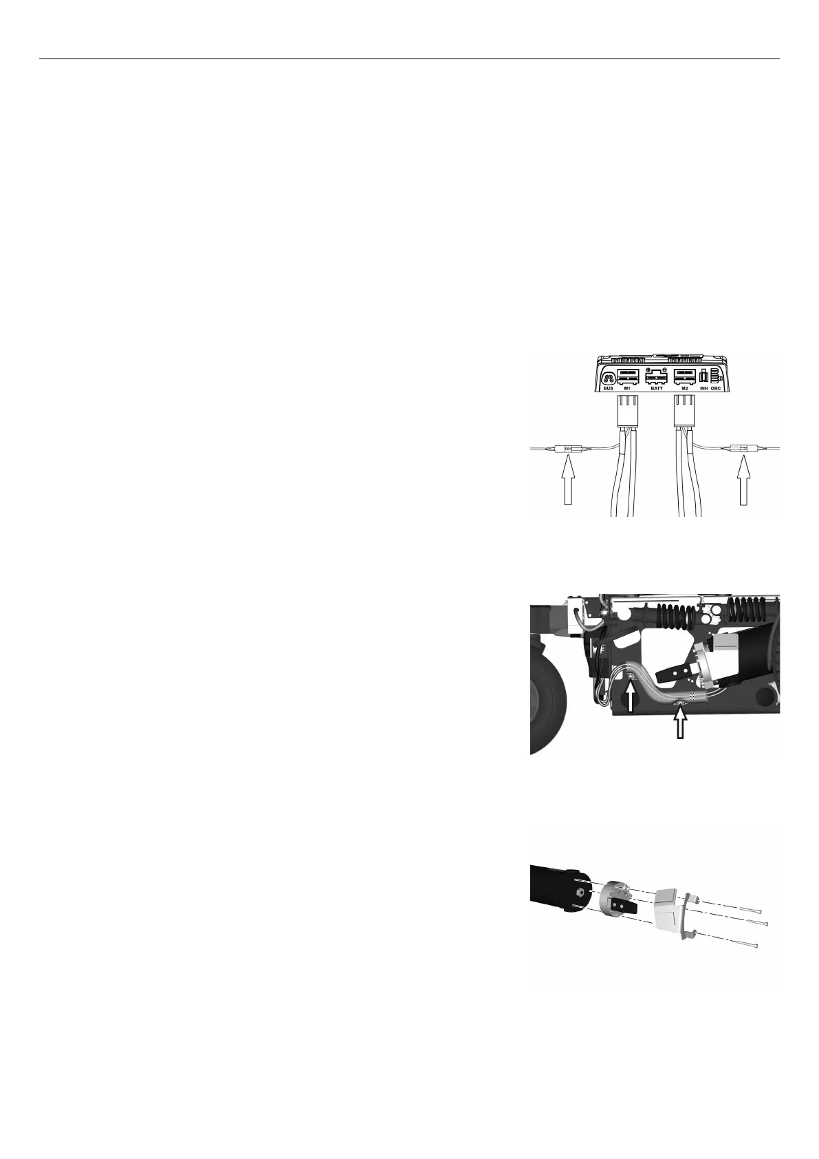
Figure 430. The magnetic wheel lock is fitted with three
screws.
6. Remove the magnetic wheel lock, it’s fitted with three screws.
143