1
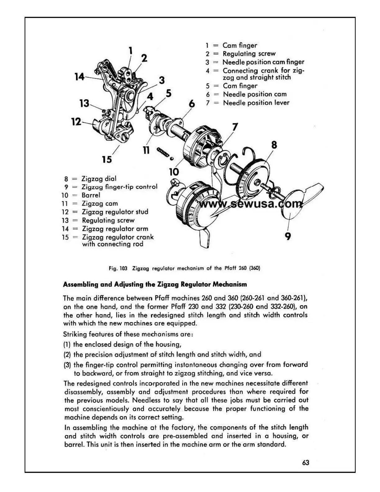
1 - Cam finger
Regulating screw
2 -
3 =
4
Needle
position
cam
finger
Connecting
crank
for
zig-
zag
and
straight
stitch
12
8 Zigzag dial
9 Zigzag finger-tip control
10 Barrel
11
Zigzag com
12
- Zigzag regulator stud
13
Regulating screw
14 = Zigzag regulator
arm
15 Zigzag regulator
crank
with connecting rod
5
= Cam
fi
nger
6 =
Needle
position cam
7
-
Needle
position lever
Fig.
103
Zigzag regulator mechanism
of
the pfaff
260
(360)
Assembling and Adjusting the Zigzag Regulator Mechanism
The main difference between Pfaff machines
260
and
360
(260-261
and
360-261},
on
the
one
hand,
and
the former Pfaff
230
and
332
(230-269
ond
332-260},
on
the
other
hand, lies
in
the
redesigned
stitch length
and
stitch width controls
with which the new machines
are
equipped.
Striking features
of
these mechanisms
are:
(1)
the enclosed design
of
the
housing,
(2)
the precision adjustment
of
stitch leng
th
and
stitch width,
and
(3)
the finger-tip control permitting instantaneous changing
over
from forward
to backward,
or
from
straight
to
zigzag
stitching,
and
vice versa.
The redesigned controls inc
orpo
rated
in the new machines nec·essitate different
disassembly, assembly
and
adjustment procedures than
where
required for
the previous models. Needless to soy
that
all these jobs must
be
carried
out
most conscientiously
and
accu
rately .
because
the
proper
functioning
of
the
machine
depends
on
its
correct
setting.
In
assembling the machine
at
the factory, the components
of
the stitch length
and
stitch width controls
ore
pre-assembled
and
inserted in a housing,
or
barrel. This unit is then inserted
in
the
machine
arm
or
the
arm
standard.
63