685408006D 33
2. General inside control temperature: 25~45
3. Start the heater at 5 and stop at 15 (optional)
4. Energy- saving mode for internal fan
5. RS 485 remote communication
6. 4~20 mA analogue output
7. Start-up self-check and real-time self-check
8. Free inspection function (optional for annual self-inspection)
9. Condensate evaporator (optional)
10. IP55 protection class
11. One- man quick installation (only for DTI)
12. Humidity detection ( optional)
13. Smog detection ( optional)
14. Flooding detection ( optional)
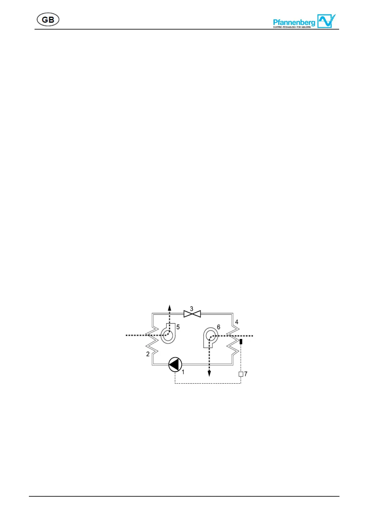
7.2 Operating principles
The compressor (1) compresses the refrigerant until high pressure is achieved. During this process
temperature increases. In the condenser (2) heat is dissipated to ambient air, the coolant becoming liquid. The
condenser fan (5) takes ambient air in through the condenser, and then it releases the air.In the expansion
valve (3) the pressure of the coolant drops. In the evaporator (4) the coolant absorbs heat from the air in the
switch cabinet and evaporates. Thus, the air in the switch cabinet cools down. At the same time the air inside
the switch cabinet is being dehumidified. The evaporator fan (6) sucks the air out of the switch cabinet via the
evaporator, the cooled air flows back to the switch cabinet.
The cooling unit is electronically controlled. For that purpose a temperature sensor records the temperature
of the air inside the switch cabinet (7).
The refrigerant is not detrimental to the ozonosphere; it is hardly combustible.
7.3 Condensate
During cooling, the moisture romoved from the hot air by the evaporator is collected as condensate. In order
to avoid any damage to the switch cabinet and the cooling unit, the condensate must be discharged.
The condensate is discharged in the following way:
In case of normal condensate drainage a reservoir (option) collects the condensate which is then drained by
means of a hose.
Always ensure that the condensate is drained properly (safety- drainage).