EN – 17
ENMaintenance
C1 series pump: The sight glass is made of glass: gradually tighten the two
attachment screws in alternation to avoid placing the sight glass under
stress.
Reassembling
the oil casing
(see page N – 6)
Reassembling the oil
level sight glass
(see page N – 2)
Fit the oil casing (6) equipped with its o-ring (11) on the frame (42).
Tighten it with screw (9) and washers (10) ( after making sure that the seal is positioned
in its seal groove).
Place the o-ring (5) in its groove and fit the sight glass (4), the flat ring (4a) (according
to the model), the oil sight glass cover (3) and tighten with screws (2). Comply with the
recommended tightening torque.
Reassembling
the gas ballast
(see page N – 2)
Position the oil case feed-through (49) equipped with its o-ring (48) in its housing by
centering it on the gas ballast tube (46). Assemble using the screws (52).
Equip the adjustment knob (55) with the sleeve (53) and the spring (54). Position
the assembly in the cover (58) and secure on the oil case feed-through (49) with
screws (57).
a
d
c
b
Check that the nozzle is not blocked by sending a jet of compressed air through it.
Reassembling
the oil system
Reassembling the
exhaust valve cover
(see page N – 6)
Reassembling the
bubble device
C2 pump (see page N – 20)
Spinner-cam, SD and SDI pumps
(except 1015 SD)
(see page N – 16)
Spinner-cam settings
Oil pump, I, C1 and C2 pumps
(and 1015 SD)
(see page N – 14)
Oil pump settings
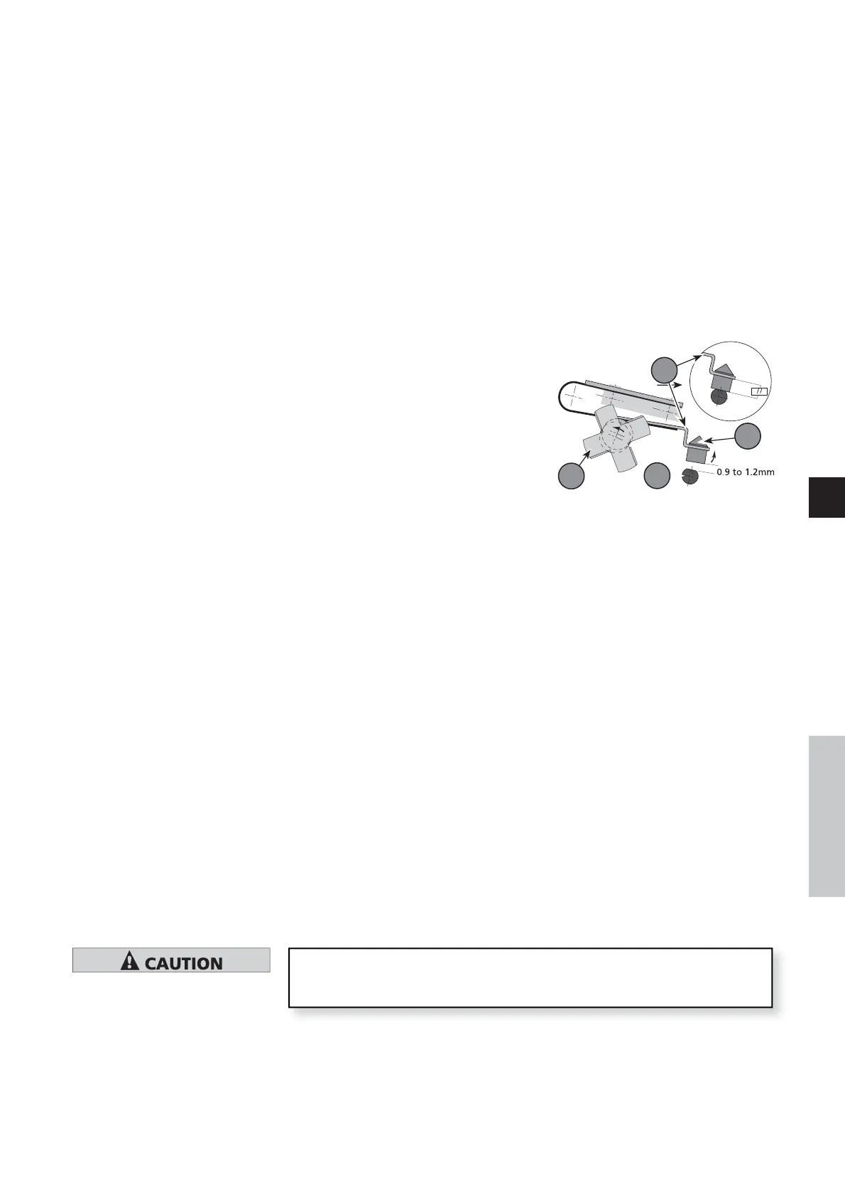
Place the spinner-cam system on the rear plate (4) and fix it with the clips (7).
Offset the spinner-cam (a) by pressing on the
blades.
Turn the shaft up to the maximum
displacement of the lever (b).
The distance between the seat (c) and the
stop valve (d) must be 0.9 to 1.2 mm (0.035
to 0.047 inch): it is set by adjusting the
orientation of the lever.
The stop valve face must be perpendicular to
the axis of the oil inlet hole; when free,the
stop valve should rest on its seat: check the parallelism of the lever in relation to the
bearing face of the stop valve seat. Orient the seat to obtain the correct setting.
In the rear plate (7), place the Oldham coupling (5), the vane (4) and the rotor (3).
Screw the seat (9) equipped with its O-ring (8). Place the piston (11) with its antisck-
back device (10), the spring (12), the cylinder (13) and the washer (14).
Position the rotor of the oil pump so that the slot is horizontal (or parallel with the
pump base). To turn it, use the fan.
Pump in a horizontal position, pour a small quantity of oil beforehand around the
exhaust valve holes.
Place the valves (2) or (11) equipped with the springs (3) or (12)
Place the valve covers (6) or (17) and fix them with screws and washers.
Insert the bubbler (8) equipped with its o-ring in the frame.
Position the tube fastener (9) on the pin and tighten the nut on the rear plate (7).
Insert the ball (4), the spring (5) in the coupling (2) and tighten it on the connector (6).