HC 75C
7-3
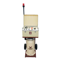
POWER SECTION DESCRIPTION
The following is a brief description of the various parts of the HC test set.
Performs all monitoring and control functions for the HC Test Set.
Input Power Indicator,
LMP201
Indicates that Input Power is applied to the test set.
Control Power Switch,
SW201
Applies 120-Volt AC Power to all of the controls in the test set.
Provides overload protection for the primary side of the control
power transformer T201.
Provides overload protection for the secondary side of the control
power transformer T201.
Provides overload protection for the vernier motor controller.
Variable Transformer
Circuit Breaker, CB202
Provides overcurrent protection for the variable transformer output
brushes. This circuit breaker must be energized for INTLK to be
cleared.
Main Circuit Breaker,
CB201
Applies Input Power to the transformers and relays. An under-
voltage safety release is tied to the interlock circuit for safety
purposes. If the interlock light is lit on the front panel, then the main
circuit breaker cannot be turned on. If, during the operation of the
test set, the interlock opens, the main circuit breaker will trip.
Emergency Off Button,
SW202
De-energizes the output and the main circuit breaker. Control
power will remain energized, and also part of the interlock circuit.
Connect to the facility ground with the Ground Cable (see #15)
Connect appropriate power to the test set.
Connect between the chassis ground terminal and the facility
ground.
Connection to the circuit breaker under test.
For use in contact mode, i.e. Normally Closed or Normally Open.
Controls the vernier speed.