HC 75C
5-1
SECTION 5: INSTALLATION INSTRUCTIONS
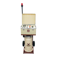
1. Position the test set in the desired position. For 2-cabinet units, place the regulator cabinet on top
of the transformer cabinet.
The following procedure is only required for 2-cabinet units (HC-12C and HC-20C):
a. Connect the interconnect ground cable from the regulator cabinet to the
transformer cabinet.
b. Connect the four interconnect power leads from the regulator cabinet to the
transformer cabinet, connecting B1 to B1, B2 to B2,
c. Connect the control interconnect cable from CON208 on the regulator cabinet to
CON209 on the transformer cabinet.
The following procedure is only required for models HC-12C, HC-20C and HC-40C:
d. Check the input power jumper configuration in both the Regulator and
Transformer cabinet. It is VERY important that these are set correctly. See the
tag on the inside panel of the unit and the following page.
2. Connect a #4 AWG ground cable from a good electrical ground to CON201 (green Cam-Lock
connector). An additional ground stud is provided on the transformer cabinet for an optional
connection of an external ground cable.
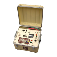
3. Position the HC Controller (on top of the cabinet works well) and connect the computer
interconnect cable. Take special care not to pinch or damage the interconnect cable. Next, plug
the HC Controller into the provided ground fault outlet and position all wires and cables behind
the controller to prevent catching or snagging during movement.
4. Ensure that the main input circuit breaker (CB201), control power switch (SW201) and vernier
circuit breaker (CB202) are all in the OFF position.
5. Connect the input power cables to CON202 and CON203 (black Cam-Lock connectors), and then
to the facility power. See the Specifications section for input ratings. Generally, cable sized
thermally for the current listed in the specifications (30 minute duty) is sufficient.
6. Perform the Power On Procedure as described in Section 6.