241B4LPY LCD 23
DDC Instructions
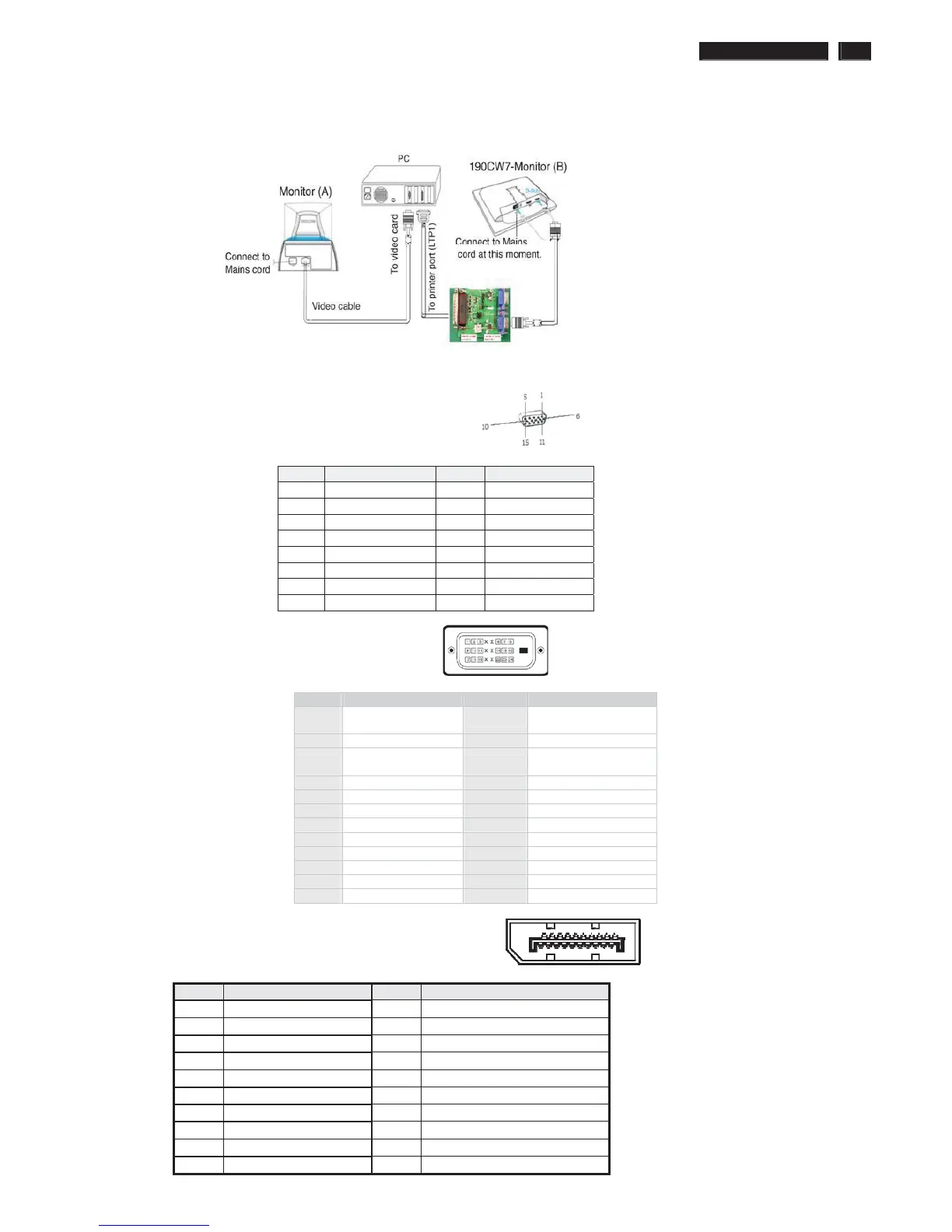
5. Connect and Mains cord to Monitor as shown in Fig.2.
Fig.2
Pin assignments:
A. 15-pin D-Sub Connector
B. Input DVI Connector pin
Pin Signal Assignment Pin Signal assignment
1
TMDS RX2-
13 Floating
2 TMDS RX2+ 14 +5V Power
3 TMDS Ground 15
Self-test (Cable
detector)
4 Floating 16 Hot Plug Detect
5 Floating 17 TMDS RX0-
6 DDC Clock 18 TMDS RX0+
7 DDC Data 19 TMDS Ground
8 Floating 20 Floating
9 TMDS RX1- 21 Floating
10 TMDS RX1+ 22 TMDS Ground
11 TMDS Ground 23 TMDS Clock+
12 Floating 24 TMDS Clock-
C. Input Display Port Connector pin
Pin Si
PWR
PIN No. SIGNAL PIN No. SIGNAL
1 Red 9 DDC +3.3V or +5V
2 Green/ SOG 10 Logic GND
3 Blue 11 Sense (GND)
4 Sense (GND) 12 Bi-directional data
5 Cable Detect (GND) 13 H/H+V sync
6 Red GND 14 V-sync
7 Green GND 15 Data clock
8 Blue GND
ʳʳ