Mechanical Instructions
EN 17LC8.1U LA 4.
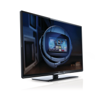
4.3.4 Woofers (ME8 styling only)
Refer to next figure for details.
1. Remove the screws [1] and [2] and lift the whole unit from
the back cover.
Take the speakers out together with their casing. When
defective, replace the whole unit.
Figure 4-13 Woofer
4.3.5 Tweeters (ME8 styling only)
Refer to next figure for details.
Warning: The speakers should never be connected or
disconnected when the set is playing! This can damage the
amplifiers on the SSB.
1. Unplug connector [1].
2. Remove screws [2] and remove unit.
Note: After repair, be sure to place the cable tapes (see also
cable dressing figures for the exact location).
Figure 4-14 Tweeter
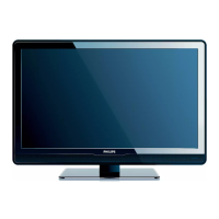
4.3.6 IR & LED Board
Refer to next figure for details.
1. Unplug connectors [1].
2. Use a flat screw driver to release the clip by pushing it in
the indicated direction [2].
3. Lift the board and take it out of the set.
When defective, replace the whole unit.
Figure 4-15 IR & LED Board
4.3.7 Key Board
Refer to next figure for details.
1. Unplug the key board connector from the IR & LED board.
2. Remove the screws [1].
3. Lift the unit and take it out of the set.
When defective, replace the whole unit.
Figure 4-16 Key Board
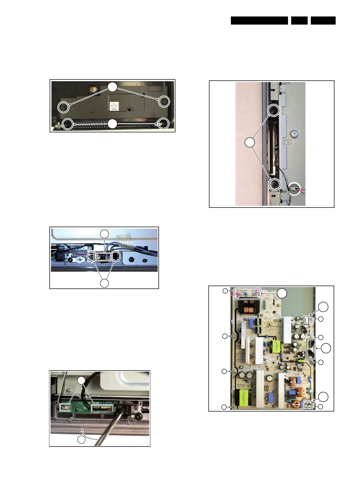
4.3.8 Display Supply Panel
Refer to next figure for details. Note: depending on the set
execution, the used PSU can differ from figure below.
1. Unplug connectors [1].
2. Remove the fixation screws [2].
3. Take the board out.
Figure 4-17 Display Supply Panel
H_17740_023.eps
230108
32
31
H_17650_095.eps
180108
2
1
H_17650_098.eps
180108
2
1
H_17650_094.eps
180108
1
H_17740_021.eps
230108
1
1
2
2
2
2
2
2
2
2
1
1
 Loading...