Mechanical Instructions
EN 11TCM3.1A LA 4.
2010-Jun-25
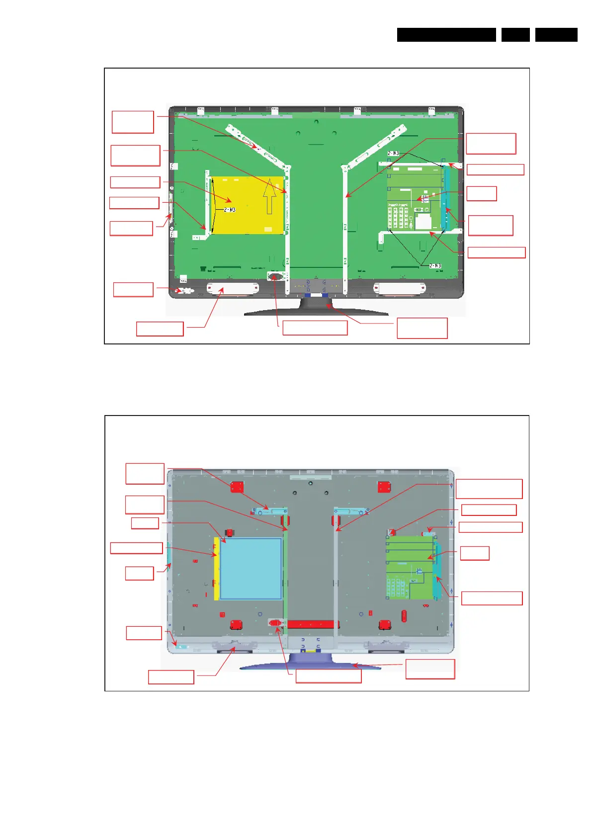
Figure 4-7 Mechanical layout 42" model
Figure 4-8 Mechanical layout 47" model
4.4 Set Re-assembly
To re-assemble the whole set, execute all processes in reverse
order.
Notes:
• While re-assembling, make sure that all cables are placed
and connected in their original position.
• Pay special attention not to damage the EMC foams in the
set. Ensure that EMC foams are mounted correctly.
42 Mechanical layout definition
SIDE AV
bracket
SSB
Button
IR - LED
Stand
bracket
2 * Speaker
AC-In Bracket
IPB
VESA
400*400
IPB bracket
Panel
bracket L
Panel
bracket R
SSB bracket B
SSB bracket U
18520_102_090318.eps
090318
47 Mechanical layout definition
Button
IPB bracket
IPB
Panel
bracket L
VESA
400*400
Panel bracket R
SSB bracket L
SSB bracket R
SSB
Side AV bracket
2 * Speaker
AC-In Bracket
IR - Lens
Stand
bracket
18520_103_090318.eps
090318







 To Next Page