Do you have a question about the Philips 48OLED935/12 and is the answer not in the manual?
Details about the diagonal screen size and display resolution.
Specifies the operating system as Android Pie 9.
Lists aerial input, tuner bands, DVB standards, and satellite input details.
Information on supported video formats and refresh rates.
Details on TV side and bottom connections like USB, HDMI, LAN, etc.
Covers connections, USB file systems, playback formats, and codecs.
Information on mains power, ambient temperature, and power saving features.
Crucial safety regulations and precautions to follow during TV repair.
Important warnings regarding electrostatic discharge (ESD) and high voltage measurements.
General notes on measurements, schematic conventions, and spare parts.
Introduction and information on handling BGA ICs.
Guidelines and rules for using lead-free soldering during repairs.
How to identify different Bill of Materials using the serial number.
Guidance on deciding whether to replace or repair a defective board.
Essential practical precautions for service technicians.
Comprehensive list of abbreviations used in the manual.
Diagrams showing cable routing for different OLED series.
Step-by-step instructions for removing the stand and rear cover.
Overview of different service modes like SAM, Factory, and CSM.
Purpose, specifications, activation, and navigation of SAM.
Purpose, specifications, and activation of the factory mode.
Purpose and specifications for CSM, used for customer diagnosis.
Procedures for updating TV software using .pkg and .upg files.
Introduction to error codes, how to read the error buffer, and overview.
Table mapping panel types to set option codes for configuration.
High-level functional block diagram of the platform.
Overview of the platform's power architecture.
Detailed power tree diagram showing voltage distribution.
Layout of the Small Signal Board (SSB) with component labels.
Functional block diagram for the MT5599KFEQ scaler IC.
Functional block diagram for the NT72334TBG/BA scaler IC.
DCA Package pinout and description for the TAS5753MDDCAR audio IC.
TSSOP-14 package pinout and block diagram for the AD22653B audio IC.
Functional block diagram for the SI2169-D60-GMR tuner IC.
Circuit diagram for the 715GA942 Power Supply Unit, Input stage.
Circuit diagram for the 715G9892 Power Supply Unit, AC Input stage.
Circuit diagram for the 715GB392M Small Signal Board (SSB), SOC-EMMC section.
Schematic for the 715GA039 IR Board, showing IR and STB LED & Light sensor circuits.
Schematic for the 715GA334 Keyboard control panel, including key definitions.
Circuit diagram for the 715GB037 Audio Board, showing speaker connections.
Circuit diagram for the 715GA036 AMBI Panel, showing G5031 IC connections.
Circuit diagram for the 715GA004 AMBI Panel, showing G5031 IC connections.
Circuit diagram for the 715GB157 AMBI Panel, showing TLC5971 IC connections.
Circuit diagram for the 715B129 AMBI Panel, showing TLC5971 IC connections.
Circuit diagram for the 715B130 AMBI Panel, showing TLC5971 IC connections.
Circuit diagram for the 715B253 AMBI Panel, showing G5031 IC connections.
Circuit diagram for the 715B253 AMBI Panel, showing G5031 IC connections.
Circuit diagram for the 715B255 AMBI Panel, showing G5031 IC connections.
Circuit diagram for the 715GB174 AMBI Panel, showing TLC5971 IC connections.
Circuit diagram for the 715GA032 AMBI Panel, showing TLC5971 IC connections.
Circuit diagram for Ambilight 9-LED functionality.
Circuit diagram for Ambilight 9-LED functionality.
Circuit diagram for the 715GB175 AMBI Panel, showing speaker connections.
Circuit diagram for Ambilight 9-LED functionality.
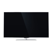
Styling information for the 48-inch OLED935 series TV.
Styling information for the 55-inch OLED805 series TV.
Styling information for the 55-inch OLED855 series TV.
Styling information for the 55-inch OLED865 series TV.
Styling information for the 55-inch OLED935 series TV.
Styling information for the 65-inch OLED805 series TV.
Styling information for the 65-inch OLED855/865 series TV.
Identifies appliances covered by the dismantling procedure, specifically LCDs.
Outlines WEEE directive requirements for storing and transporting LCDs.
Lists hazardous substances potentially found in LCDs and PCB assemblies.
| Screen Size | 48 inches |
|---|---|
| Display Technology | OLED |
| Resolution | 4K Ultra HD (3840 x 2160) |
| Refresh Rate | 120 Hz |
| Smart TV | Yes |
| Operating System | Android TV |
| HDMI Ports | 4 |
| USB Ports | 2 |
| Ambilight | Yes |
| Sound System | Bowers & Wilkins |
| Processor | P5 AI Perfect Picture Engine |
| Sound | 50W |
| Wi-Fi | Yes |
| Bluetooth | Yes |
| HDR Support | HDR10, Dolby Vision |




 Loading...