Service Modes, Error Codes, and Fault Finding
EN 22 BP2.2U, BP2.3U5.
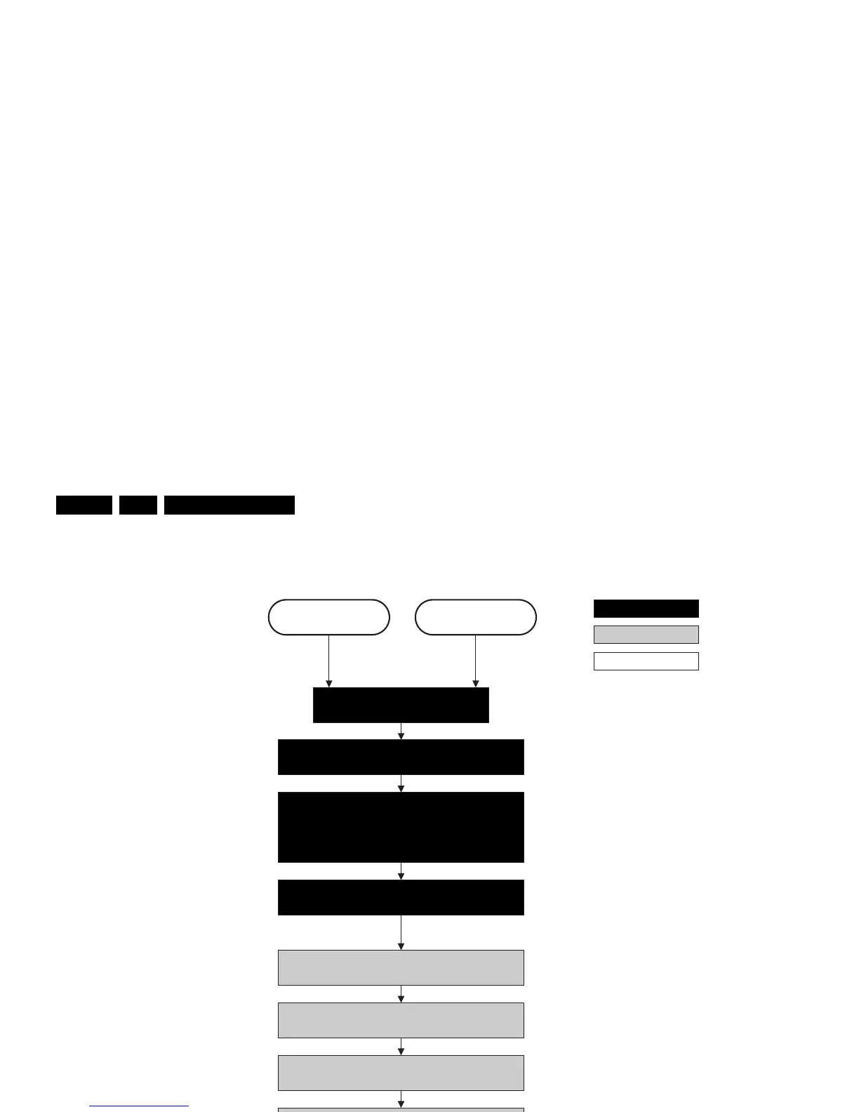
Figure 5-8 “Semi Stand-by” / ”POD” to “Stand-by” flowchart
Transfer Wake up reasons to the
Stand- by µP.
Images are re-transferred to DDR-RAM from
Flash RAM (verification through checksum).
Stand-by
Semi Stand-by
action holder: MIPS
autonomous action
action holder: St-by
MIPS image completes the application reload,
stops DDR-RAM access, puts itself in a
sleepmode, and signals the standby µP when
the Stand-by mode can be entered.
Disable all supply related protections and switch “off”
the +2V5, +3V3 DC/DC converter.
DDR-RAM is put in self refresh mode and the images
are kept in the hibernating DDR-RAM.
Switch “off” all supplies by switching “high” the POD-
MODE and the ON-MODE I/O lines.
Switch Viper in reset state
Important remark:
release RESET AUDIO and
SOUND_ENABLE 2 sec after
entering stand-by to save power
POD
Switch “off” the remaining DC/DC converters
Wait 5ms
Wait 5ms
For PDP this means
CPUGO becomes low.
Wait 10ms
Switch the NVM reset line “high”.
F_15400_099.eps
260505