EasyManua.ls Logo

Philips FC 880 - Installation

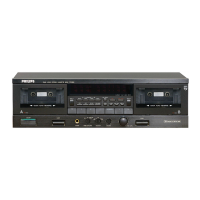
Philips FC 880
44 pages
To Next Page IconTo Next Page
To Previous Page IconTo Previous Page
Loading...
English
INTRODUCTION
Thank
you
for
selecting
the
Philips
FC880
Stereo
cassette
deck
for
your
audio
system.
This
cassette
deck
incorporates
a
number
of
features
designed
to
enhance
your
enjoyment
of
your
favorite
audio
programs.
Please
read
these
operating
instructions
carefully.
We
recommend
that
you
read
the
entire
owner’s
manual
before
you
attempt
to
connect
or
operate
the
unit.
After
you
have
read
the
contents
of
this
manual,
we
suggest
that
you
make
all
system
connections
before
you
attempt
to
operate
the
unit.
INSTALLATION
e
After
unpacking
remove
all
protective
materials.
@
Do
not
leave
the
equipment
and
the
cassettes
for
any
length
of
time
in
direct
sunlight
or
other
places
where
high
temperatures
can
occur,
such
as
in
the
vicinity
of
heating
apparatus.
@
Do
not
expose
the
equipment
to
humidity
or
rain.
@
This
unit
is
equipped
with
microprocessors.
Static
electricity,
for
example,
may
sometimes
cause
interference.
You
can
correct
this
by
switching
off
the
mains
switch
for
30
seconds.
@
Always
place
the
cassette
deck
on
a
horizontal
surface.
@
If
your
cassette
deck
is
placed
on
or
close
to
other
equipment,
hum
may
sometimes
occur.
A
different
position
can
eliminate
the
interference.
FEATURES
1.
Dolby
HX-Pro
The
Dolby
HX-Pro
system
dramatically
expands
the
tape
recording
performance
and
greatly
improves
the
high-
frequency
recording
oharacteristic.
With
an
ordinary
fixed
bias
recording
circuitry,
the
use
of
a
low
bias
can
improve
the
high-frequency
MOL,
but
increases
the
overail
distortion.
On
the
other
hand,
a
high
bias
can
reduce
distortion,
but
the
high-frequency
MOL
is
degraded.
As
a
result,
in
case
the
recorded
music
contains
a
large
amount
of
high-frequency
component,
the
effects
of
the
high-frequency
cornponent
and
fixed
bias
are
multiplied
resulting
in
over-bias,
which
degrades
the
high-frequency
saturation
level.
This
tendency
is
worsened
when
the
recording
level
is
high.
To
avoid
this
situation,
the
Dolby
HX-Pro
system
detects
the
high-frequency
component
contained
in
the
signal
to
be
recorded
and
controls
the
recording
bias
accordingly.
The
saturation
level
characteristic
is
improved
by
reducing
the
bias
high-frequencies,
while
maintaining
the
effective
bias
for
the
middle
and
iow
frequencies.
This
makes
it
possible
to
obtain
reproduction
performance
with
headroorn
close
to
that
of
Metal
tapes,
from
normal-
position
tapes.
It
is
to
be
noted
that,
unlike
noise
reduction
systems,
the
Dolby
HX-Pro
system
is
a
recording
bias
adjustment
system
which
functions
only
during
recording.
Consequently,
cassettes
recorded
with
the
Dolby
HX-Pro
system
can
be
played
back
at
any
other
cassette
deck.
2.
Dolby
B
and
C
noiso
roduction
systems
The
Dolby
NR
(Noise
Reduction),
systems
reinforce
low-
level
signals
in
the
high
and
middle
frequencies
to
a
certain
extent
during
recording,
and
attenuate
these
signals
to
the
same
extent
during
playback.
As
a
result,
the
signal
as
recorded
is
reproduced,
except
that
the
tape
hiss
usually
generated
in
tape
recording
is
largely
reduced.
The
principle
of
the
Dolby
C
NR
system
is
similar
to
that
of
the
previously-released
B
type
but,
while
the
B
type
reduces
noise
by
about
10
dB,
the
new
C
type
achieves
about
20
dB
reduction,
which
is
three
times
greater.
Note:
The
[tpIrt
effect
of
Dolby
B
and
C
NR
systems
is
obtained
only
when
the
same
type
of
NR
system
is
used
in
both
recording
and
playback.
If
one
is
used
only
in
recording
or
playback,
or
if
different
types
are
used
in
recording
and
playback,
the
high
frequencies
will
be
degraded,
causing
unnatural
sound.
3.
MPX
filter
Switch
the
MPX
(Multiplex)
filter
ON
when
recording
FM
radio
broadcasts.
The
MPX
filter
suppresses
the
19
kHz
pilot
signal
contained
in
the
FM
transmission
and
thereby
prevents
Dolby
NR
malfunction.
4.
Digital
Peak
Level
indicator
and
Memory
Call
function
The
input
level
of
the
recording
signal
is
quantized
by
an
8-bit
A/D
converter,
and
displayed
digitally
in
real
time
in
the
range
from
0
dB
to
+12
dB
in
1
dB
steps.
When
the
‘DISPLAY’
button
is
pressed,
the
maximum
peak
level
is
indicated
by
a
flashing
displayuntil
the
button
is
pressed
again.
This
facilitates
recording
level
setting
so
that
the
recording
can
make
full
use
of
the
tape
performance.
5.
Programmed
Playback
and
Programmed
Dubbing
Up
to
sixteen
music
tracks
selected
from
the
just
fifteen
tracks
on
a
tape
can
be
programmed
in
any
desired
order
and
played
back.
The
programme
can
also
be
recorded
on
another
tape
in
Programmed
Dubbing.
5.
Parallel
Recording
and
Continuous
Recording
Using
both
decks,
simultaneous
recording
(Parallel
Recording)
and
sequential
recording
(Continuous
Recording)
are
possible.
7.
Quick
Reverse
An
infrared
sensor
detects
the
beginning
of
the
leader
tape
and
reverses
the
tape
quickly.
CONNECTIONS
Figure
1
For
safety
reasons
it
is
necessary
to
consult
your
dealer
for
the
connection
of
equipment
without
a
recorder
connection
e.g.
TVs.
@
‘L-OUT
and
R-OUT'
line
outputs
For
connecting
the
cassette
deck
to
the
inputs
‘TAPE
1.
L+R
IN’
or
‘TAPE
2
L+R
IN’
of
the
amplifier.
@)
‘L-IN
and
R-IN’
line
inputs
For
connecting
the
cassette
deck
to
the
outputs
‘TAPE
1
L-R
OUT’
or
‘TAPE
2
L+R
OUT’
of
the
amplifier.
©
In
and
output
for
remote
control
‘REMOTE
CONT.
BUS
IN/OUT’
Socket
©
'IN’
can
be
connected
with
the
‘REMOTE
OUT’
of
your
amplifier,
if
this
is
equipped
with
a
corresponding
socket
for
remote
control.
Socket
©
‘OUT’
can
be
inter-
connected
with
your
tuner,
record
player
or
compact
disc
player
if
this
is
equipped
with
a
corresponding
socket
for
remote
control.
©
Mains
cable
For
connecting
the
cassette
deck
to
the
mains.
The
type
plate
is
located
on
the
rear
of
the
deck.
3
{
:
i
;
;
j
z
!
A
eI
a
mE
Ae
EFT
eG
OT
aN
TE
PEPE
EEN
Pe
IE
ele
RE
OT
POTD
Ee
PE
EA
EO
Et
eRe
Pe)
NS
ee
ET
Fe
RT
Te
FO
RMN

Related product manuals