EN 31
3139 785 32540
Dismantling Instructions & Service Positions
4.
4.4 Service Positions
Notes: The AVIO (SCART) bracket 135, the HDMI bracket
134 and the rear frame 132 should be removed for main
unit service positions. Refer to the set-wiring diagram for the
correct cable connection between boards.
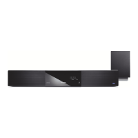
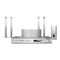
Figure 4-27
Service Position 1
MPEG Board, AV Board, AVIO Board, Door Control Board and
HDMI Board
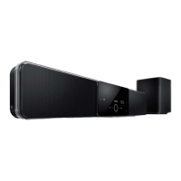
Figure 4-28
Service Position 2
Front Display Board and Door Control Board
HDMI Board
Insulation Sheet
AVIO (/37/59)
or SCART (/05/12)
Board
Door Control Board
Front Display Board
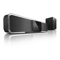
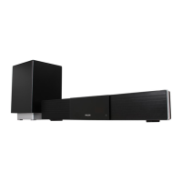
Figure 4-29
Service Position 3
IPOD Board and USB Board
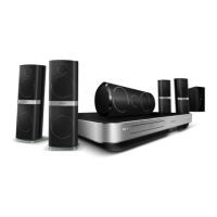
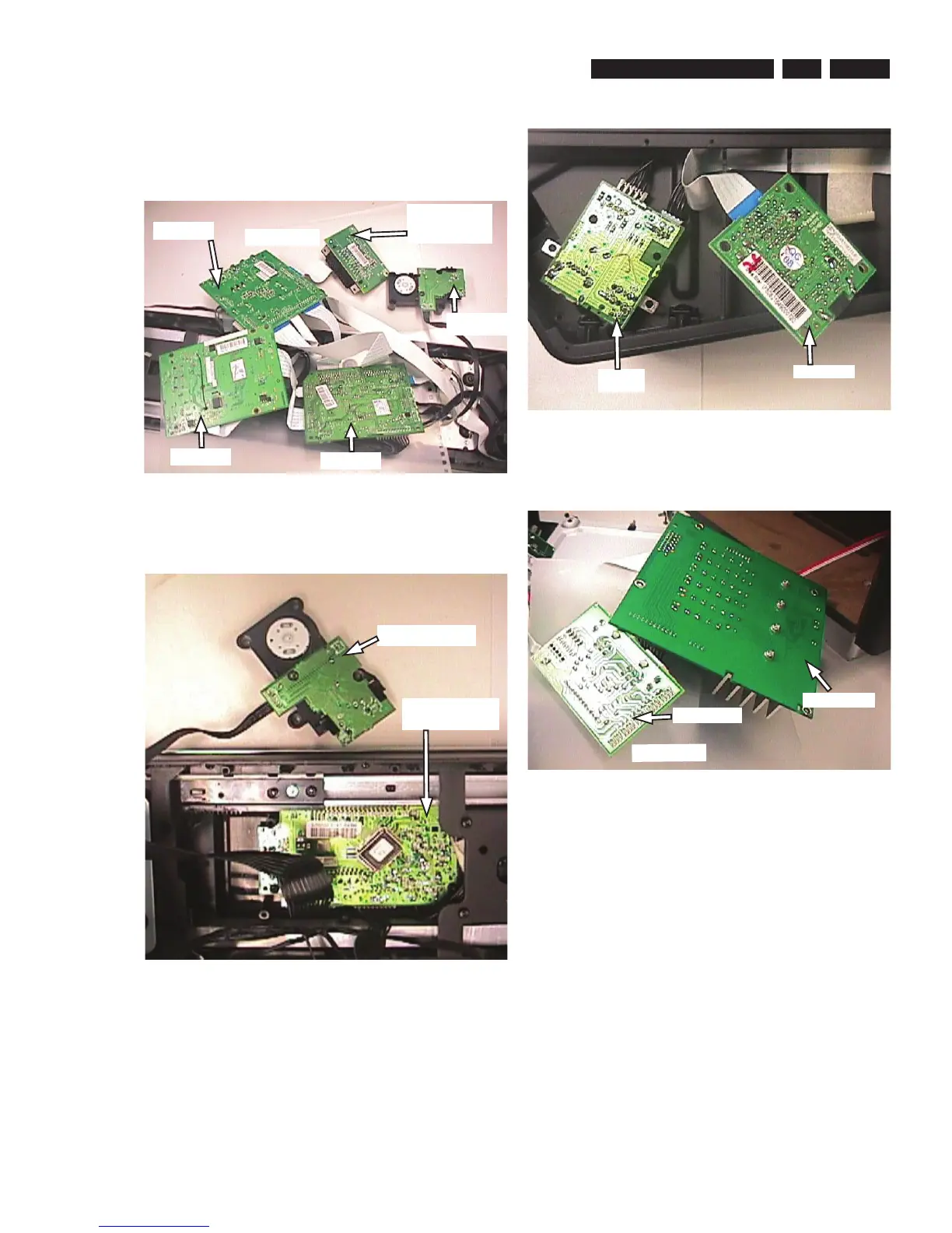
Figure 4-30
Power Box Service Position 4
Amplifi er Module and Speaker Board
USB Board
IPOD Board
AV Board
MPEG Board
Door Control
Board
Insulation Sheet
Speaker Board
Amplifi er Module
 Loading...