B
ASIC
TV
AND
R
EMOTE
C
ONTROL
O
PERATION
3
1
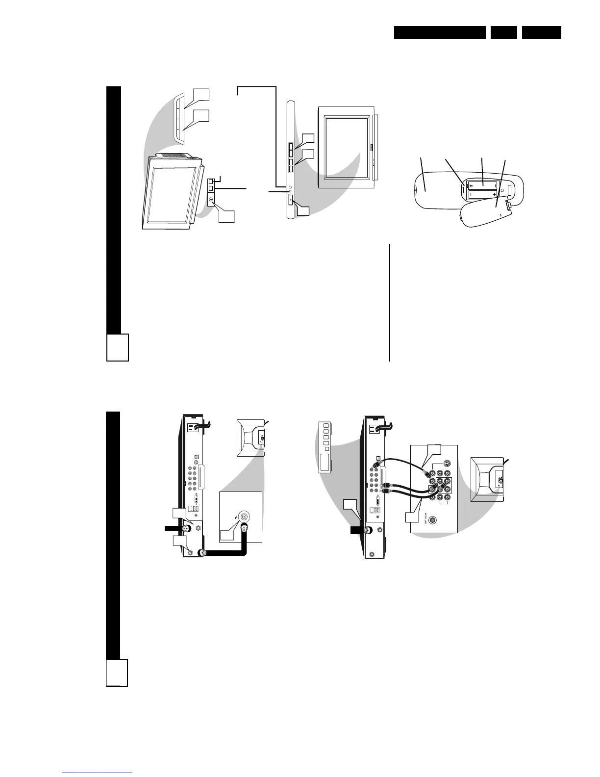
Press the POWER button to
turn the TV ON.
Note: You can also press any
button on the front of the TV to
turn the TV ON.
2
Press the VOLUME + button
to increase the sound level, or
the VOLUME – button to
lower the sound level.
Pressing both buttons at the
same time will display the on-
screen menu. Once in the
menu, use these buttons to
make adjustments or selections.
3
Press the CHANNEL UP + or
DOWN – button to select TV
channels.
4
Point the remote control
toward the remote sensor win-
dow on the TV when operating
the TV with the remote.
REMOTE CONTROL
T
o load the supplied batteries
into the remote:
1. Remove the battery compart-
ment lid on the back of the remote.
2. Place the batteries (2-AA) in
the remote. Be sure the (+) and (-)
ends of the batteries line up correct-
ly (inside of case is marked.)
3. Reattach the battery lid.
Battery Compartment
2-AA Batteries
Battery Lid
Back of Remote
Standby Light Indicator - Red light will show
when in the Standby Mode. Press the Power
button to return the TV to it’s active state.
Remote Sensor - Sensor for
activating remote control com-
mands when the remote is
used to control the TV.
Example of Models 27PT6441/37 and 27PT6442/37
Example of Models 27PT5441/37 and 32PT5441/37
CABLE BOX CONNECTIONS
2
I
f your cable signal uses a cable
box or decoder, follow the easy
steps below to complete the connec-
tion.
Cable Box (w/RF In/Outputs):
This connection will be mono.
1
Connect the Cable Company
supplied cable to
the signal
IN(put) plug on the back of the
Cable Box.
2
Using a separate round coaxial
cable, connect one end to the
OUT(put) (TO TV) plug on the
back of the Cable Box.
3
Connect the other end of the
round coaxial cable to the 751
input on the back of the televi-
sion. Screw it down finger tight.
NOTE: If applicable, set the OUT-
PUT CHANNEL SWITCH on the
back of the cable box to CH 3 or 4.
Tune the TV to the same channel and
change channels at the cable box. In
some cases, the cable box will auto-
matically tune to either channel 3 or 4,
change channels until the picture
appears.
Cable Box (w/Audio/Video
Outputs):
This connection will supply Stereo
sound.
4
Connect the Cable Company
supplied cable to
the cable sig-
nal IN(put) plug on the back of
the Cable Box.
5
Using a RCA type Video Cable,
connect one end of the cable to
the Video (or ANT, your cable
box may be labeled differently)
Out jack on the cable box and
the other end to the AV1 Video
Input on the TV.
6
Connect one end of the Audio
Left and Right Cable to the left
and right Audio Out L & R
jacks on the cable box. Connect
the other end to the AV1 Audio L
& R Input jacks on the TV.
NOTE: Use the AV button on the TV
remote control to tune to the AV1
channel for the cable box signal. Once
tuned, change channels at the cable
box, not the television.