Circuit Descriptions, List of Abbreviations, and IC Data Sheets
EN 87L04L AA 9.
• IR. This input pin is connected to an RC5 remote control
receiver.
• SEL-IF-LL’/ M-TRAP. For AP: All L04 AP sets are Multi
System QSS set. This is an output pin to switch the Video
SAW filter between M system and other systems.
– 0: NTSC M (default)
– 1: PAL B/G, DK, I, L
• Write Protect. The global protection line is used to enable
and disable write protection to the NVM. When write to the
NVM is required, pin 7 of the NVM must be pulled to logic
‘0’ first (via Write_Protect of the micro-controller pin) before
a write is performed. Otherwise pin 7 of NVM must always
be at logic “1”
– 0: Disabled
– 1: Enabled (default)
• Mute. This pin is use to MUTE the audio amplifier. It is
configured as push pull.
• Rotation. This pin is configured as PWM for the Rotation
feature. The output of the PWM is proportional to the
feature control.
• Light Sensor. This pin is configured as ADC input for the
Light Sensor.
• Sel_SC2_Interface. This pin is use to switch between the
SC2_CVBS_OUT and the INTF_CVBS_OUT for the
SCART_2_CVBS_OUT/ MONITOR_OUT signal.
– 0: Hercules CVBS Output (default)
– 1: Interface CVBS Output
• PWRDOWN. The AUX SMPS generates this signal. Logic
“high” (3.3 V) under normal operation of the TV and goes
“low” (0 V) when the Mains input voltage supply goes below
70 V_ac.
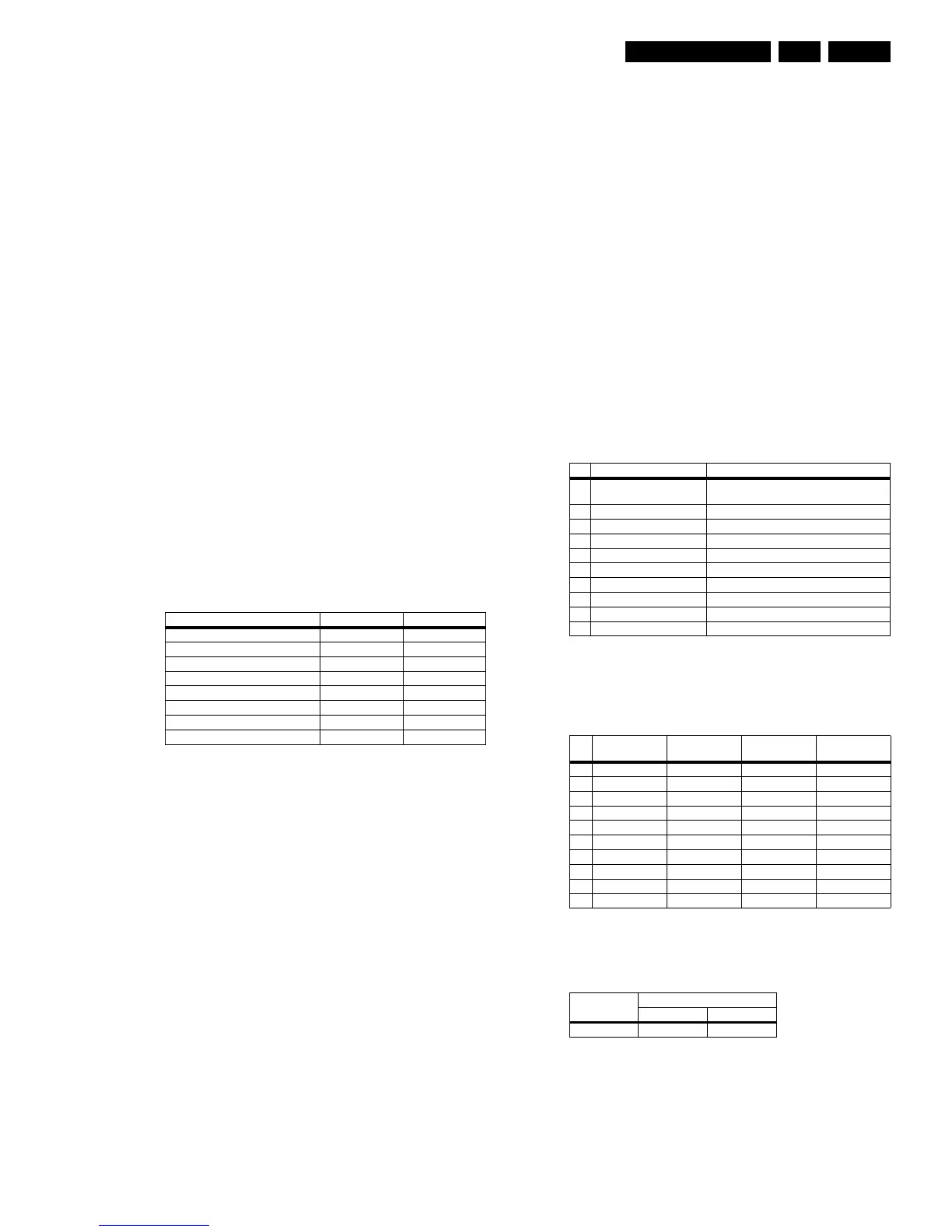
• Keyboard. Following are the Keyboard functions and the
step values (8 bit) for it.
Table 9-6 Local keyboard values
• SDM. This pin is configured as Open Drain during the cold
start only. If this pin is shorted to ground during cold start,
it will enter the SDM mode (for Service use).
• ISP. This pin is configured as Open Drain during the cold
start only. If this pin is shorted to ground during cold start,
it will enter the ISP mode (for Service use).
• PANEL. This pin is configured as Open Drain during the
cold start only. If this pin is shorted to ground during that,
then it will enter to the PANEL mode.
• ResetEnabled. This is an output pin to switch the control
transistor (pos. TS7202) “high” or “low” for the reset of 1.8
V in case there is a corruption in the Hercules.
9.5 Tuner and IF
The tuner used in this chassis comes from two sources, from
Philips and from Alps. Both tuner sources have the same pin
configuration so they are 1 to 1 compatible except for the
software, which will be selected by means of Option Settings.
Some features:
• Multi-Standard alignment free PLL-IF, including SECAM
L/L’.
• Integrated IF-AGC time constant.
• Integrated sound band-passes and traps (4.5 / 5.5 / 6.0 /
6.5 MHz).
• Group delay compensation (for NTSC and for PAL).
• QSS versions with digital Second-Sound-IF SSIF (AM
demodulator for free).
• FM mono operation possible: Inter-Carrier or QSS.
9.5.1 Diversity
The following Tuners can be present (depending on the region
and the set execution):
• Normal tuner without PIP.
• FM radio tuner without PIP.
• Normal tuner with PIP (main tuner with splitter).
• FM radio set with PIP (PIP tuner with splitter).
The SAW filter used, depends on the application concept
(whether it is a QSS concept or an Intercarrier):
• OFWM3953M for QSS Video.
• OFWK9656M for QSS Audio.
• OFWM1971M for Intercarrier.
9.5.2 Pin Assignments and Functionality
Pin assignment of the Tuner:
Table 9-7 Pinning Tuner
Pin assignment of the several SAW filters (depends on region/
execution):
Table 9-8 Pinning SAW filters
The table below shows the switching behavior of SAW filter.
Table 9-9 Switching behavior SAW filter
Note: The logic level is measured at the base of transistor
7001.
Function Voltage (V_dc) Step values (8 bit)
NAFTA Standby 0 0 - 6
Ch + 0.43 7 - 33
Exit Factory (Ch- and Vol-) 0.69 34 - 53
Ch - 0.93 54 - 73
Menu (Vol - and Vol +) 1.19 74 - 96
Vol - 1.49 97 - 121
DVD Eject 1.8 122 - 147
Vol + 2.12 148 - 169
Pin Pin Description DC Voltages
1 RF-AGC 4V for Maximum Gain < 4V for Strong Signal
Condition
2 FM Radio Input or N.C -
3 NC (Address Pin) -
4 SCL 0 to 3.3 V_dc
5 SDA 0 to 3.3 V_dc
6/7 Supply Voltage 5 V_dc +/- 0.25 V
8N.C -
9 Tuning Supply Voltage 30 to 35 V_dc
10 FM Radio IF Output/Ground -
11 TV IF Output -
Pin
QSS Video
(item 1002)
QSS Video
(item 1003)
QSS Audio
(item 1001)
Intercarrier
(item 1002)
1 Input Input Input Input
2 Input Ground Input Ground Switching Input Input Ground
3 Ground Ground Ground Ground
4 Output Output Output Output
5 Output Output Output Output
6- n.c. - -
7- n.c. - -
8 - Ground - -
9- Free - -
10 - Switching input - -
Condition
High Low
System M BG/DK/I/L