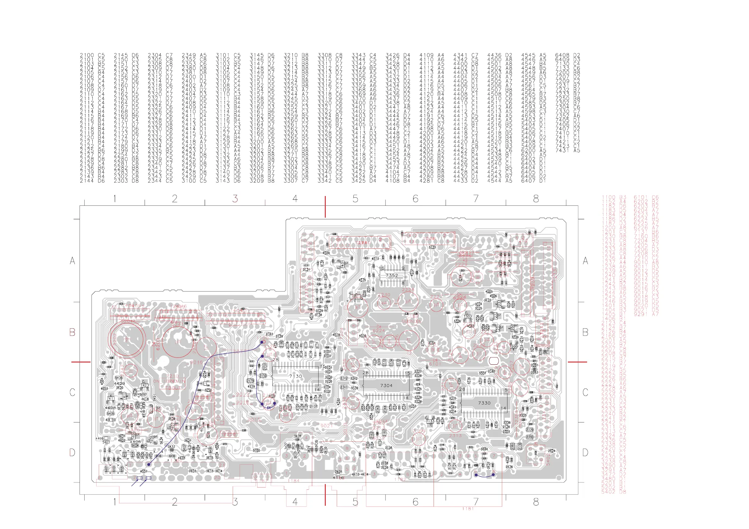
BOTTOM VIEW - SMD & COMPONENT
PART A
PART B
PART C
PART D
2 chip cap 4,7nF
The following reworks are make at prod. start-up on the SMD side:
1. 2 chip cap 4,7nF (4822 126 13193) added across Scart connector pins
2/4 and 4/6.
2. Wire added between Scart pin 5 to ground pin 1100.
3. Wire added between Elco 2126 -ve pin and 2123 -ve pin.
4. Zener diode BZX79-C12 (4822 130 34197) is added across Elco 2123
with the cathode to the +ve pin.
5. Wire added between EMC ground to Dig ground below the Digital In/Out
socket 1181
3139 113 3500 pt5 dd wk318
This assembly drawing shows a summary of all possible versions. For components used in a specific version see schematic diagram and respective parts list
9-6
9-6