Interconnectivity
Page 11 of 14
PDIUSBD12 Evaluation Board (PC Kit) User’s Manual REV. 2.1
_______________________________________________________________________________________________
Philips Semiconductors - Asia Product Innovation Centre
Visit http://www.flexiusb.com
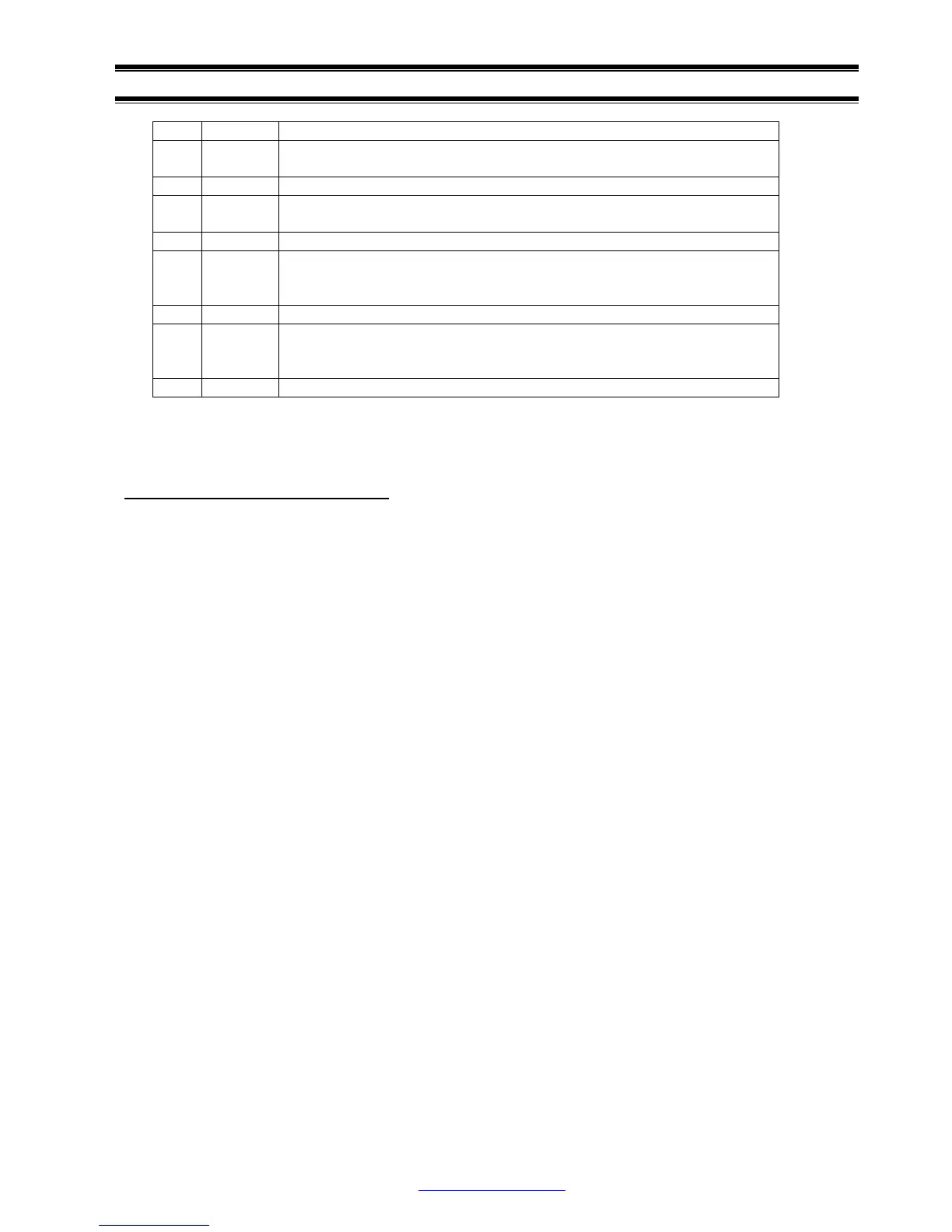
17 I/O DATA0
18 I T/C, Terminal Count: This line provides a pulse when terminal count
for any DMA channel is reached. This signal is active high.
19 I ADDR2
20 I -DACK: This line is used to acknowledge DMA request and is active
low.
21 I ADDR1
22 O DRQ: This line is asynchronous channel request used by peripheral
devices to gain DMA service. A DMA request is generated by bringing
DRQ line to an active high.
23 I ADDR0
24 O IRQ: This line is raising edge triggered. An interrupt request is
generated by raising this line high and hold until it is acknowledged by
the processor.
25 POWER GND
PAL Equations
Address and command decoder
/** Inputs **/
Pin 1 = ADDR2;
Pin 2 = ADDR1;
Pin 3 = ADDR0;
Pin 4 = !IOW;
Pin 5 = !IOR;
Pin 6 = !DACK;
Pin 7 = !AD_EN;
Pin 8 = RESET;
Pin 9 = INT_N;
Pin 11 = INT_EN;
/** Outputs **/
Pin 12 = IRQ;
Pin 13 = RESET_N;
Pin 14 = RD_N;
Pin 15 = WAIT;
Pin 16 = !CS_D12;
Pin 17 = !WR_273;
Pin 18 = !RD_244;
Pin 19 = !DIR_245;
/** Logic Equations **/
!DIR_245 = (!AD_EN & !DACK) # !IOR # RESET;
!RD_244 = !AD_EN # !(!ADDR2 & ADDR1 & !ADDR0) # !IOR;
!WR_273 = !AD_EN # !(!ADDR2 & ADDR1 & ADDR0) # !IOW;
!CS_D12 = !AD_EN # !(!ADDR2 & !ADDR1) # (!IOW & !IOR);
RESET_N = !RESET;
IRQ = !INT_N & INT_EN;
WAIT.OE = CS_D12;
WAIT = RESET;
RD_N = !IOR;