Interconnectivity
Page 9 of 14
PDIUSBD12 Evaluation Board (PC Kit) User’s Manual REV. 2.1
_______________________________________________________________________________________________
Philips Semiconductors - Asia Product Innovation Centre
Visit http://www.flexiusb.com
HARDWARE DESCRIPTION
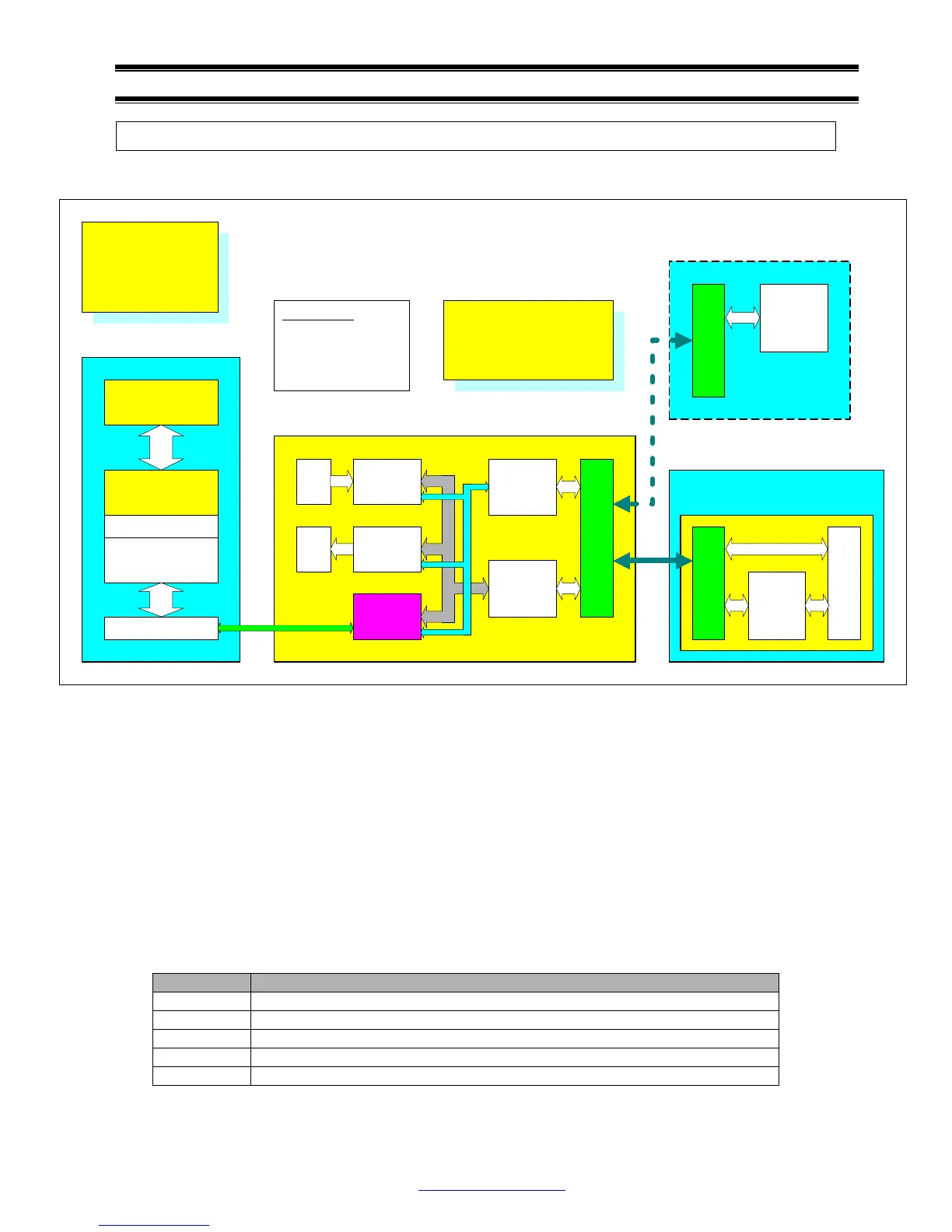
Block Diagram
Above block diagram shows 5 main components on the PDIUSBD12 evaluation board. Beside bus
transceiver, address/command decoder and PDIUSBD12, a general input port and a general output
port are included in the design. These input and output ports are designed for test purposes, such as
test switches and test LEDs. They also act as glue logic to adapt the PDIUSBD12 to the ISA bus. For
example, ISA interrupt is edge triggered, but PDIUSBD12 interrupt is level triggered. The MSB of the
general output port is used as interrupt enable to convert level triggered interrupt to edge triggered.
I/O Mapping
PDIUSBD12 evaluation board uses 8 I/O addresses:
Offset Usage
0 D12 data register, R/W
1 D12 command register, W only
2 General input port, R only
3 General output port, W only
4 to 7 Reserved for expansion board
USB Host Controller
USB Host Controller
Driver
USBD
D12 Sample Driver
D12TEST.SYS
D12 Sample Applet
D12TEST.EXE
PDIUSBD12
Bi-direction
Bus
Transceiver
Command
and Address
Decoder
General
Output port
General
Input port
Test
Key
Test
LED
25
Pin
I/F
25
Pin
I/F
ISA
Slot
DIP
Switches
and
Jumpers
25
Pin
I/F
CPU,
Memory,
and DMA
Controller
USB Host PC
D12 Evaluation Board
USB Device PC
Customer's System
25 Pin Interface
1. VCC, GND
2. D0 - D7
3. ADDRESS ENABLE
4. IOW, IOR, IRQ, RESET
5. DREQ, DACK, EOT
On USB host side, a
sample application program
D12TEST.EXE and a
general purpose minidriver
D12TEST.SYS are
provided.
On device side, sample firmware
D12FW.EXE is provided for
running on device PC. The
firmware is written in C for easily
portable to other CPU platforms.
D12 ISA Bridging Board
System Block
Diagram of D12
Evaluation Kit