Interconnectivity
Page 5 of 14
PDIUSBD12 Evaluation Board (PC Kit) User’s Manual REV. 2.1
_______________________________________________________________________________________________
Philips Semiconductors - Asia Product Innovation Centre
Visit http://www.flexiusb.com
Installation
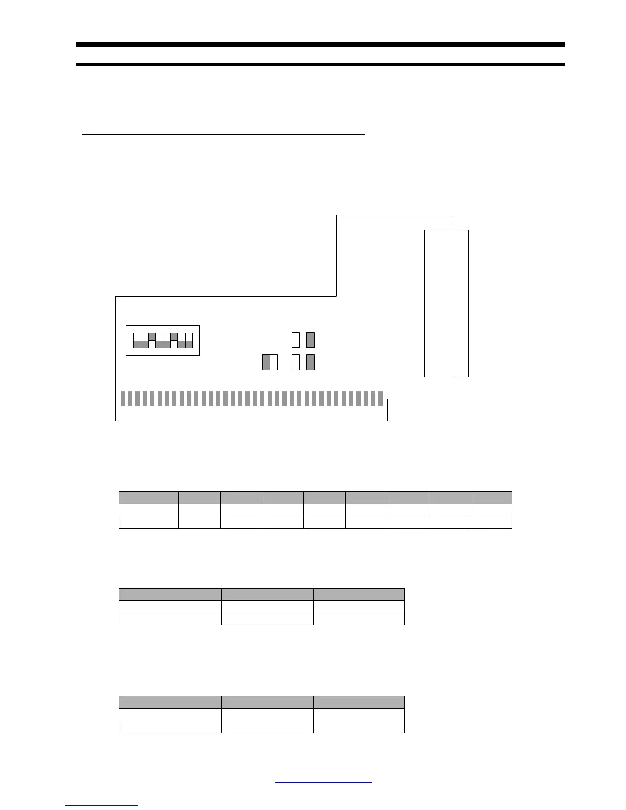
Jumper’s setting on PDIUSBD12 ISA bridging board
The PDIUSBD12 ISA bridging board is plugged inside the device PC. It will occupy I/O, IRQ and DMA
resources of the device PC. To avoid possible conflicts in settings, we suggest removal of all the
unnecessary cards from the device PC. Sound card and network card may cause conflict in IRQ and
DMA setting.
Switch S1 sets the base I/O address for the D12 evaluation board. Default base address is 0x368.
The D12 evaluation board occupies 8 I/O locations. A0 to A2 are decoded on the D12 evaluation
board. Switch S1 sets the address decoding of A3 to A9. Please notice that a switch ‘ON’ is logic ‘0’.
SW(n) 1 2 3 4 5 6 7 8
Address X A3 A4 A5 A6 A7 A8 A9
Default OFF OFF ON OFF OFF ON OFF OFF
Jumpers JP1 and JP2 set the IRQ number for the D12 evaluation board. Default setting is IRQ5 or
JP1 is shorted.
IRQ Number IRQ5 IRQ7
Jumper’s Setting JP1 JP2
Default ON OFF
Jumpers JP3 to JP6 set the DMA number for the D12 evaluation board. Default setting is DMA3 or
JP4 and JP6 are shorted. Please note that a respective pair of jumpers is needed to set a particular
DMA channel.
DMA Number DMA1 DMA3
Jumper’s Setting JP3, JP5 JP4, JP6
Default OFF, OFF ON, ON
J2
S1
1 8
JP1 JP2 JP3 JP4
JP5 JP6