18440_216b_090227.eps
270209
Yes
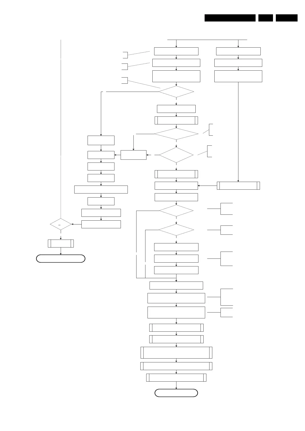
MIPS reads the wake upreason
from standbyµP.
Semi-Standby
Initialize tuner and Multi Standard decoder
Initialize video processing IC's
:
-localcontrast FPGA
-PNX5100(ifpresent)
Initialize source selection
Initialize AutoTV
3-th try?
Blink Code as
error code
Bootscript ready
in 1250 ms?
Yes
No
Enable Alive check mechanism
Wait until AVC starts to
communicate
SW initialization
succeeded
within 20s?
No
Switch Standby I/O line high
and wait 4 seconds
RPC start (comm. protocol)
Set I²C slave address
of StandbyµPto(60h)
Yes
Disable all supply related protectionsand
switch off the +3V3 +5V DC/DC converter.
switch off the remaining DC/DC
converters
Wait 5ms
Switch AVC PNX8543
in reset (active low)
Wait 10ms
Switch the NVM reset
line HIGH.
FlashtoRam
image transfer succeeded
within 30s?
No
Yes
Code =
Layer1: 2
Layer2: 53
Code =
Layer1: 2
Layer2: 15
Initialize Ambilight with Lights off.
Timing need to be updated if
more mature info isavailable.
Timing needs to
be updated if more
mature info is
available.
Timing needs to be
updated if more
mature info is
available.
Initialize audio
Enter protection
Reset-system isswitched HIGH bythe
AVC attheendofthebootscript
AVC releases Reset-Ethernet when the
end of the AVC boot-script is detected
This cannot be done through the bootscript,
the I/O is on the standbyµP
Reset-system is connectedtothe
Micronas MultiStandard decoder.
Reset-Audio and Audio-Mute-Up are
switched byMIPS code lateroninthe
startup process
Reset-system isswitched HIGH bythe
AVC attheendofthebootscript
AVC releases Reset-Ethernet when the
end of the AVC boot-script is detected
Reset-Audio and Audio-Mute-Up are
switched byMIPS code lateroninthe
startupprocess
Switch on the displayincaseofa LED backlight
display by sending the TurnOnDisplay(1) (I²C)
command to the PNX5100
In caseofa LED backlight display, a LED DIM panel is present
which is fed bytheVdisplay. To power the LED DIM Panel, the
Vdisplay switch driven by the PNX5100 must beclosed. The
display startup sequence is taken care of bytheLEDDIM
panel. Secondly,
this cmd will alsoenable the LVDS outputof
the 5100 towards the LED DIM panel.
Enable the PWM output towards the displayLVDS
cable in caseofa LED Backlight set.
(CTRL4-PNX5100)
In caseofa LED backlight display, the PWM-dimming signal
needs to berouted to the LVDS cable. This routing is not
allowed in non-LED sets (see alsodisplay configuration)
Wake upreason
coldboot & not semi-
standby?
5100 SW start
MIPSsends displayparametersand
Bitmap to 5100
Startup screen cfg file
present?
MIPS triggers 5100 to displaythe
startup screen
Startup screen visible
yes
yes
To keep this flowchart readable, the exact displayturn on
description is not copied here. Please see the Semi-standby
to On description for the detailed display startup sequence.
During the complete displaytimeoftheStartup screen, the
preheat condition of 100% PWM is valid.
No
No
Startup screen shall only bevisible when there isacoldboot
to an active state end situation. The startup screen shall not
bevisible when waking upforreboot reasons or waking upto
semi-standby conditions.
The firsttimeafter the option turn on of the startup screen or
when the set is virgin, the cfg file is not present and
hence
the startup screen will not be shown.
From: 18440_216a_090227.eps
From: 18440_216a_090227.eps