Circuit Descriptions
EN 41Q548.1E LA 7.
2009-Apr-03
7.2 Power Supply
All power supplies described below are a black box for Service.
When defective, a new board must be ordered and the
defective one must be returned, unless the main fuse of the
board is broken. Always replace a defective fuse with one with
the correct specifications! This part is available in the regular
market.
Consult the Service Spare Parts website for the order codes of
the boards.
7.2.1 Specifications
Most sets in the TV543 platform use the Integrated Power
Board (IPB) - incl. inverter. The 52" sets in this chassis have a
conventional PSU - with separate inverter.
In this Service Manual, no detailed information is available
because of design protection issues.
7.2.2 Diversity
Below find an overview of the different PSUs that are used:
Table 7-1 Supply diversity
7.2.3 Application
An application diagram can be found below:
Figure 7-3 Application Integrated Power Board
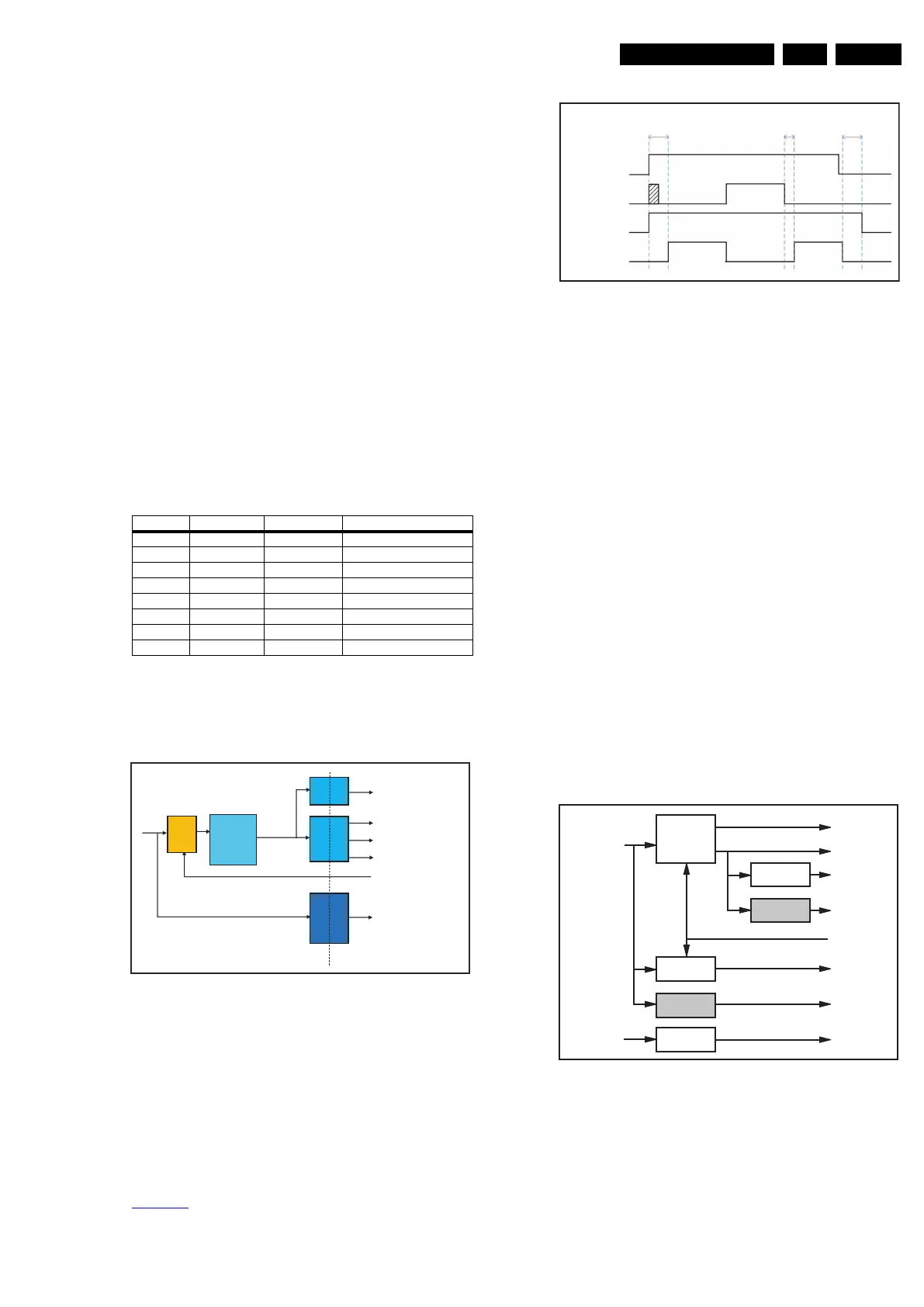
7.2.4 Power Supply Timing
The STANDBY signal controls the on-mode voltages +12V,
+V
snd
and +24V. During chassis cold start from AC mains,
+12V can be expected to be stable within 1.0 seconds, while for
a warm start, i.e. wake up from stand-by power state, this
timing becomes 0.5 seconds maximum. During AC switch off,
stand-by power +3V3-STANDBY decay is at least 20 ms but
not more than 5.0 seconds compared to +12V. Refer to
Figure 7-4
:
Figure 7-4 PSU Timing Diagram
7.2.5 Power Supply Protection
Power supply protection is implemented via the stand-by
controller of the PNX8543 via the following signals:
• POWER-OK: signal from PSU to indicate if the supply
output from the IPB is normal
• DETECT1: signal to indicate if the +5V, +3V3 and +1V2
voltages on the chassis are present
• DETECT2: signal to indicate if the +12V voltage on the
chassis is present.
7.3 DC-DC Converter
Input power is obtained from the IPB module via the following
voltages:
• +3V3-STANDBY (stand-by-mode only)
• +12V (on-mode)
•+V
snd
(audio power) (on-mode)
• +24V (bolt-on power) (on-mode).
Control is achieved by the PNX8543 controller via the
STANDBY signal.
Audio power is specifically for audio supply usage only and
does not go through any DC conversion.
Below find a block diagram of the on-board DC-DC converters.
Figure 7-5 DC-DC converters
Supplier PSU Model Input Voltage Range
LGIT PLHL-T826B 32PFL7404H/12 High Mains (198 to 265 V
AC
)
Delta
DPS-298CP-4 A 42PFL7404H/12 High Mains (198 to 265 V
AC
)
Delta
DPS-298CP-2 A 47PFL7404H/12 High Mains (198 to 265 V
AC
)
Delta DPS-411AP-3 A 52PFL7404H/12 High Mains (198 to 265 V
AC
)
LGIT PLHL-T826B 32PFL8404H/12 High Mains (198 to 265 V
AC
)
Delta DPS-298CP A 37PFL8404H/12 High Mains (198 to 265 V
AC
)
Delta DPS-298CP-4 A 42PFL8404H/12 High Mains (198 to 265 V
AC
)
Delta DPS-298CP-2 A 47PFL8404H/12 High Mains (198 to 265 V
AC
)
Vo=400V
+3V3_STANDBY
+12V
Audio Supply (+12V)
To Lamps
AC Input
Non- Isolated/Hot
Isolated/Cold
PFC
Flyback
STANDBY
(HIIGH=OFF, LOW=ON)
RELAY
Inverter
+24V
18440_208_090226.eps
090327
18440_209_090226.eps
090227
Vin AC
STANDBY
+3V3-STANDBY
+12V, +Vsnd, +24V
Max 1.0sec Max 0.5 sec
Min 20 msec
Max 5.0 sec
+
3V3-STANDBY
+12V
+1V2-PNX8543
+3V3
+1V8-PNX8543
+1V8-PNX5100
ENABLE-3V3
+5V_+5V5-TUN
+1V2-PNX5100
18440_210_090227.eps
090227
+1V2-STANDBY
LD3985M
(Linear Regulator)
ST1S10
(Sync Power IC)
LD1117
(Linear Regulator)
LD1117
(Linear Regulator)
NCP5422 + 2x
Si4936
(Sync Dual
Controller
+ Dual FETs)
ST1S10
(Sync Power IC)