Technical Specifications and Connections
EN 3Q548.1E LA 2.
2009-Apr-03
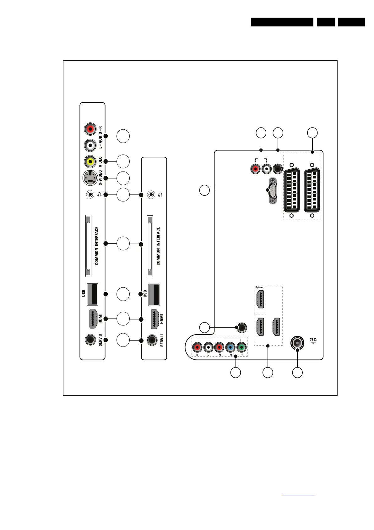
2.3 Connections
Figure 2-1 Connection overview
Note: The following connector colour abbreviations are used
(according to DIN/IEC 757): Bk= Black, Bu= Blue, Gn= Green,
Gy= Grey, Rd= Red, Wh= White, Ye= Yellow.
2.3.1 Side Connections
1 - Cinch: Audio - In
Rd - Audio R 0.5 V
RMS
/ 10 kΩ jq
Wh - Audio L 0.5 V
RMS
/ 10 kΩ jq
2 - Cinch: Video CVBS - In
Ye - Video CVBS 1 V
PP
/ 75 Ω jq
3 - S-Video (Hosiden): Video Y/C - In
1 - Ground Y Gnd H
2 - Ground C Gnd H
3 - Video Y 1 V
PP
/ 75 Ω j
4 - Video C 0.3 V
PP
/ 75 Ω j
4 - Head phone (Output)
Bk - Head phone 32 - 600 Ω / 10 mW ot
5 - Common Interface
68p - See diagram B05C SSB: PCMCIA
jk
18440_001_090217.eps
090217
Back connectors
EXT 2
(RGB/CVBS)
EXT 1
(RGB/CVBS)
SPDIF
OUT
AUDIO
VGA
TV ANTENNA
HDMI 3
AUDIO IN:
LEFT / RIGHT
HDMI 1 / DVI
HDMI 2 / DVI
HDMI 3 / DVI
VGA
EXT 3
11
12
13
10 9
14
15 16
HDMI 2 HDMI 1
OUT
1
2
6
3
4
5
7
8
26-52”
19-22”