Circuit Descriptions
EN 29TPM5.1E LA 7.
2011-Sep-02
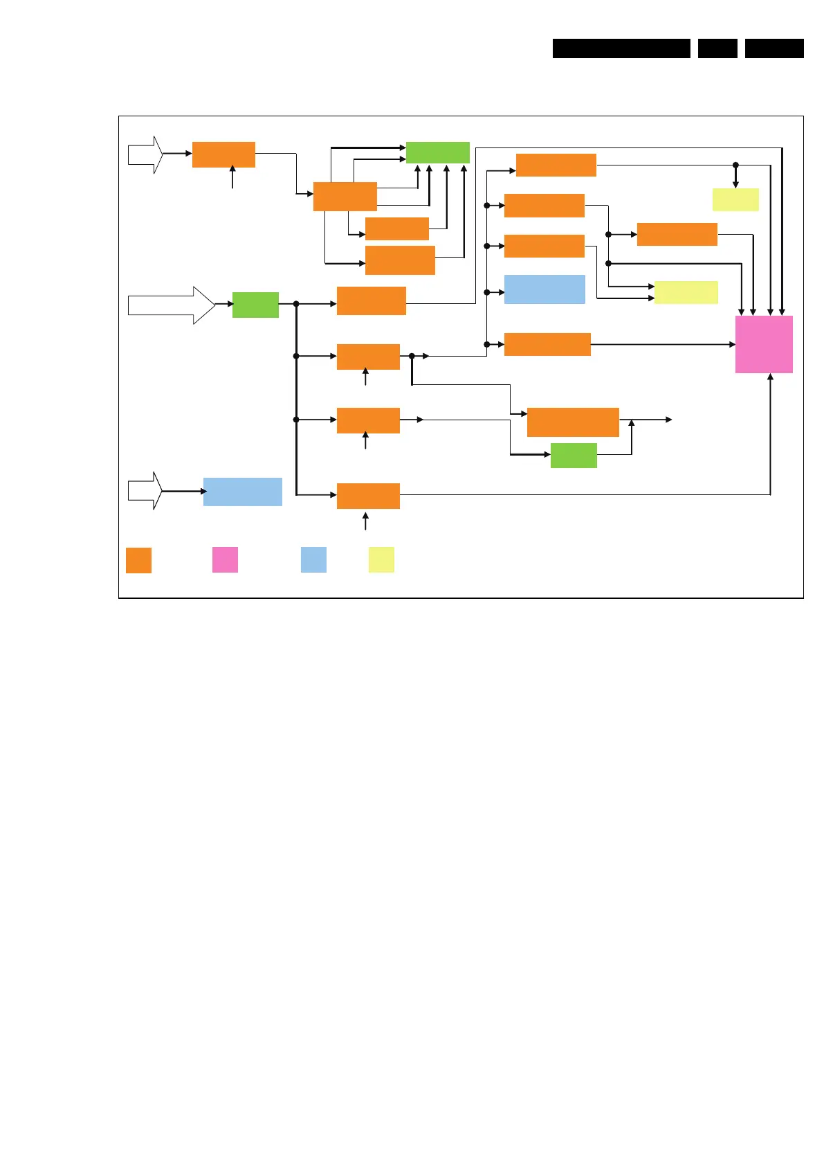
7.2 Power Architecture
Figure 7-5 Dali Power Architecture
All power supplies are a black box for Service. When defective,
a new board must be ordered and the defective one must be
returned, unless the main fuse of the board is broken. Always
replace a defective fuse with one with the correct
specifications! This part is available in the regular market.
Consult the Service website for the order codes of the boards.
The output voltages to the chassis are:
• +5-STANDBY (stand-by-mode only)
• +12V (on-mode)
• +24V (audio power)
18850_209_100204.eps
100210
+12V
STB_PWR5V
+24V
U601 TDA3110D2
Audio -Digital AMP
+24V
U601 TDA3110D2
Audio -Digital AMP
Q750 SI5441DC
CMOS
LC Circuit
U751
G1117-33T63Uf
U750
G1117 -33T43UF
PANEL_VCC_ON/OFF
DV33
Q704 SI5441DC
switvh
PANEL VCC(12V)
AV33
+5V_STB
DV18_DDR
PANEL
DV33SB
+5V_SW
Q703 SI3441
switch
DV11
+5V1_TUN
STAND BY
U702
AP1117DL_13
U752
G1117-33T43Uf
+5V_TUNER
U755
SC4215HSETRT
MT5363
5.3V
U701 MP9403
Buck
DV11
OPWRSW
Main Chip
DC to DC
Audio Other chipMain Chip
DC to DC
Audio Other chip
U753
G1117T43Uf
AV12
PCMCIA
DDR
U7053
PF57
TCON_VDD
TCON_VCC
U7054
APM1117E-18LA
TCON_1V8
U411 STMPS2171
-STR power switch
CI2_VCC
U602 TAP6132
HEADPHONE
Amplifier
Jumper
U7050
MP1484
TCON_VCC
TCON_VDD
HALF TCON_VDD
VGH
VGL